Install the MXK
50
MXK Hardware Installation Guide
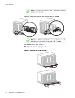
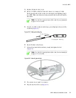
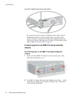
Figure 25: Complete power wires and grounding
The system is now live and ready to initialize the slot cards as they are
installed. In the absence of any slot cards, there is no activity on the
system. The power A and power B LEDs on the front panel of the unit
should be solid green, indicating power is normal. For information on the
chassis LEDs, see
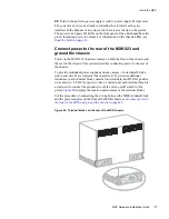
Connect power to the MXK 319 and ground the
chassis
Connecting power to the MXK 319 and grounding the
chassis
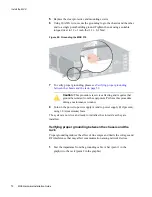
1
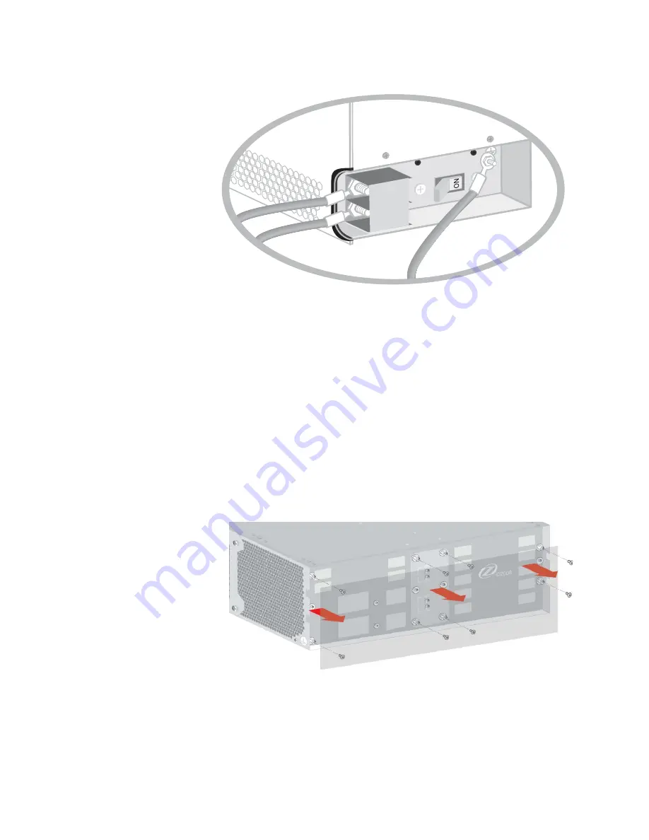
On the rear of the MXK 319 chassis, remove the eight screws which
attach the clear protective cover.
2
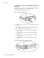
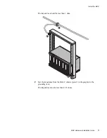
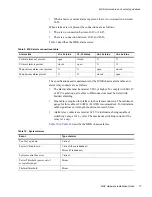
The MXK 319 chassis will accept dual redundant power feeds — A & B.
Loosen the wire clamp screws. They may be tight so use a screwdriver
with a large diameter handle.
A
RTN
-48VDC


