background image

U

SING


THE

 C

LOCK

 D

RIVE

The clock drive included with your telescope is designed to track the move-
ment of stars. It will help keep stars in your field of view during long periods 
of viewing as long as the telescope is properly polar aligned and the clock 
drive is properly used. Do not be alarmed if you turn on the clock drive and 
do not see the telescope moving. Stars appear to move very slowly and the 
telescope may not apear to move over a short period of time. To see if your 
clock drive is working, aim the telescope at a stationary terrestrial object and 
engage the clock drive. Let the clock drive run for 10 to 15 minutes. If the 
object you had originally aimed the telescope at appears to have moved when 
looking through the eyepiece of the telescope, the clock drive is working.

C

LOCK

 D

RIVE

 S

ETTINGS

The clock drive features two sets of controls which can be used to control 
the motion of the telescope The power switch doubles as the hemisphere set-
ting. If you are using the telescope in the Northern Hemisphere, the switch 
should be set to the upper position, in the Southern Hemisphere, the switch 
should be set to the lower position. The speed setting should be adjusted 
while viewing to help keep stars centered in the field of view. You may have 
to increase or decrease your speed setting if stars appear to drift in your field 
of view. You will need to adjust the clock drive based on what you are look-
ing at while viewing. As a general rule, the farther away from the celestial 
pole (closer to the horizon) an object that you are viewing is, the faster it will 
appear to move and the faster the clock drive speed will need to be set.

M

ANUAL

 A

DJUSTMENT


WITH

 C

LOCK

 D

RIVE

The clock drive included with your telescope should only be used to follow 
stars. When you would like to point your telescope at a different celestial 
object, you must disengage the clock drive. By loosening the thumbscrew 
on the clock drive R.A. axis, you will disengage the clock drive, protecting 
the clock drive and making manual adjustment easier. Manually adjusting the 
R.A. axis with the clock drive engaged may cause the gearing in the clock 
drive to strip, compromising the operation of the clock drive. When you 
would like to reengage the clock drive, simply tighten the thumbscrew and 
use the clock drive hand controller to begin tracking stars.

Summary of Contents for Tycho

Page 1: ...TYCHO 254 ...

Page 2: ... telescopes require some technical knowl edge of stellar movement and optical properties We have tried to provide the basics of telescope use and astronomical viewing in this manual If after reading through this manual you still have questions regarding the setup and use of your telescope please feel free to contact us at info zhumell com or at 800 922 2063 Our customer service representatives wil...

Page 3: ...Format 1 25 Finder Scope 8x50 Mount Type EQ5 Equitorial MOUNT Materials Aluminum R A Adjustment Manual Worm Gear Dec Adjustment Manual Worm Gear Clock Drive Axis R A and Dec Clock Drive Power 4 D cell Batteries INCLUDED ITEMS Optical Tube Assembly 8x50 Finderscope EQ5 Equitorial Mount Adjustable Speed Clock Drive with Hand Controller R A and Dec Adjustment Knobs Counterweight 2 Aluminum Tripod Acc...

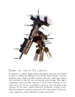
Page 4: ...tical Tube Mounting Belt 7 Focuser 8 Primary Mirror 9 Dec Adjustment Knob 10 Dec Axis Release 11 Declination Scale 12 Hour Circle R A Scale 13 Polar Alignment Scope 14 Latitude Scale 15 Latitude Adjustment 16 Counterweight 17 Counterweight Shaft TELE SCOPE LE GE ND 2 1 3 4 5 6 7 8 ...

Page 5: ...ion and soft lint free cloth Do not rub elements when cleaning Blot optical components gently and allow telescope to air dry Store telescope in box when not in use Do not use alcohol or solvents to clean any parts of the telescope Do not remove optical elements from telescope as doing so may affect the alignment of optical components when reassembled If telescope needs realignment contact Zhumell ...

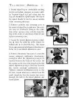
Page 6: ...crew 3 Locate the mount alignment prong extend ing up from the north leg of the tripod la belled with an N above the leg Also locate the mount rotational stabilization thumbscrews below the front latitude adjustment screw 4 Remove the mount base screw Loosen the mount rotational stabilization thumbscrews enough to allow the alignment prong to be inserted between the bases of the screws Set the mou...

Page 7: ...e thumbscrews on the counterweights until shaft opening in the counterwiegt is completely unobstructed With the thumbscrew pointing down slide the counterweight up the counterweight shaft and tighten counterweight thumbscrew until snug Repeat for each counterweight Replace the end screw of the counterweight shaft and tighten until snug 5 Loosen R A and Dec axes by turning axis release levers 180 P...

Page 8: ...the optical tube assembly by the attached handle near the focuser and set it into the optical tube mounting rings guiding it with your other hand Close the optical tube mounting rings and retighten the thumbscrews on the mounting rings to secure optical tube assembly 10 Remove nuts from finderscope mount ing bolts near the focuser on the optical tube assembly Slide finderscope mount over the bolts...

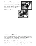
Page 9: ...e vibration when viewing at high magnification adjust the counterweight position on the counterweight shaft to offset the weight of the optical tube assembly and balance the telescope When placing the optical tube assembly into the mounting rings center the rings along the length of the optical tube assembly Centering the rings along the length of the optical tube assembly will help to keep the te...

Page 10: ... the Motor Connection Cord into the receptacle at the base of the plastic housing on the R A drive of the mount Place 4 D cell batteries into the battery pack and plug the power cord from the battery pack into the Battery Pack Connection receptacle in on the hand controller To activate the hand controller simply switch the hemisphere setting to the appropriate setting and press the desired speed a...

Page 11: ...sition in the Southern Hemisphere the switch should be set to the lower position The speed setting should be adjusted while viewing to help keep stars centered in the field of view You may have to increase or decrease your speed setting if stars appear to drift in your field of view You will need to adjust the clock drive based on what you are look ing at while viewing As a general rule the farthe...

Page 12: ...ng your telescope SOME NOTE S ON V IE WING Never look at the sun without using a solar filter When using a solar filter do not remove the full lenscap view only through the small opening in the lenscap Looking at the sun without proper use of a solar filter can cause permanent eye damage When looking through the telescope the image will appear to be upside down and inverted This results from the o...

Page 13: ...l tube assembly try adjusting the counterweight position up or down to properly balance the telescope The optical tube assembly should move very easily Do not force the optical tube assembly as you may cause damage to the telescope INTE RMED IATE OB SE RV ATION Once you are familiar with the basic movements and adjustments of the tele scope expand your exploration to other easy to find objects Ven...

Page 14: ...eia the Queen will allow you to properly align your telescope In the Southern Hemisphere you will need to use a star chart to find stars near the meridian and the ce lestial equator so that you can use the star drift method to polar align your telescope Both Northern and Southern Hemisphere alignment are described here B EF ORE GE TTING STARTED Before you begin aligning your telescope look at the ...

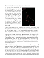
Page 15: ...olar alignment scope The objective of the polar alignment scope should be directly above the north leg of the tripod labelled with an N Turn the telescope tripod and all so that the front of the mount faces north You can use a compass to find magnetic north and then line up with Polaris celestial north or line up the front of the tele scope in line with Polaris by imagining a straight line running...

Page 16: ...34 since Sydney lies at 34 S latitude this will point you roughly at the southern celestial pole 1 Having already roughly aligned your telescope loosen the declination clamp and swivel telescope until scale reads 90 then retighten clamp Loosen the right ascension clamp and rotate telescope so that it points 6 hours away from the celestial pole and retighten clamp The R A and Dec adjustment cables ...

Page 17: ...lt of your clock drive speed setting and can be corrected by adjusting the clock drive speed 5 Unengage the clock drive Loosen the right ascension clamp and rotate the telescope back 6 hours opposite the direction you rotated it in step 1 Find a bright star in the viewfinder and center the star in the viewfinder Center this star in the highest power eyepiece as you did with the previous star Reeng...

Page 18: ...nd the polar axis 12 hours in Right Ascension until the finder is on the opposite side of the telescope If the optical axis of the finder is parallel to the polar axis of the mount then Polaris will not have moved in relation to the finderscope s crosshairs If on the other hand Polaris has moved off of the crosshairs then the finderscope will need to be aligned with the polar axis of the mount If ...

Page 19: ... Alkaid the last star in the Big Dipper To acheive accurate polar alignment the polar axis of the telescope must now be lined up with the north celestial pole 2 Loosen the R A and Dec axis clamps and aim the telescope at a star near the celestial equator with known right ascension Be careful not to move the mount base or tripod while moving the optical tube Retighten the axis clamps 3 Loosen the R...

Page 20: ...will be viewing 58 for Dubhe 63 for Acrux Retighten the clamp to lock the declination in place 2 Loosen the right ascension clamp and rotate the telescope on the R A axis until the star you are using to set the hour circle is near the center of the finderscope Retighten the clamp to lock in the R A axis 3 Center the star in the eyepiece using the R A and Dec adjustment cables Once it is centered t...

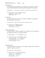
Page 21: ...ure mm Ex Focal Ratio of a 70x900mm telescope Focal Ratio F x 900mm 70mm Focal Ratio F x F 12 8 Limiting Magnitude To determine the limiting magnitude of a telescope use the aperture in the following formula for an approximation Limiting Magnitude 7 5 5LOG Aperture in cm Ex Limiting Magnitude of a 114x1000mm telescope Limiting Magnitude 7 5 5LOG 11 4cm Limiting Magnitude 7 5 5 x 1 057 Limiting Mag...

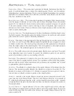
Page 22: ... equator The vernal equinox is where right ascension is at 0 h hours The autumnal equinox can be found at 12 h R A ZEN ITH The zenith is the point in the celestial sphere directly above your head The zenith varies depending upon your location In general the declination point of your zenith is equal to the latitude at which you are standing on Earth EPHEMERIS The ephemeris of a planet or the sun or...

Page 23: ... Visually the smaller the focal ratio also called f stop of a telescope the wider the field of view Photographically the lower the f stop the shorter the exposure time needed to capture an object on film LIMITING MAGNITUDE The limiting magnitude of a telescope describes the faintest object you can see with a telescope The magnitude of a star describes its brightness The larger the magnitude of an ...

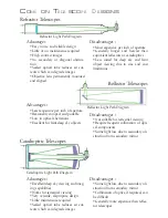
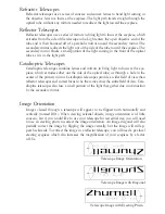
Page 24: ...tages Least expensive per inch of aperture Reasonably compact and portable Low in optical aberrations Excellent for faint deep sky objects Disadvantages Not suitable for terrestrial viewing Require frequent collimation of opti cal components Some light loss due to secondary ob struction from secondary mirror Catadioptric Telescopes Catadioptric Light Path Diagram Advantages Excellent deep sky view...

Page 25: ... to focus at the eye piece which extrudes either out the side of the optical tube or through a hole in the center of the primary mirror Catadioptric telescopes provide a wider field of view than reflector telescopes and correct focus to be the same across the entire field of view Cata dioptric telescopes also lose a small portion of the light they gather due to obstruction by the secondary mirror ...

Page 26: ...why we love you and a flaw that you have noticed may be hard to find by our techni cian A letter will speed up the warranty process and save a phone call Oh yes please include your phone number and an address Since we are constantly searching for the best products we may have improved or changed our Zhumell products from the time you first obtained yours therefore it is our option to repair or rep...

Page 27: ...m Plössl 0 965 12 5mm Plössl 0 965 17mm Plössl 0 965 20mm Plössl 0 965 25mm Plössl 1 25 6 3mm Plössl 1 25 7 5mm Plössl 1 25 10mm Plössl 1 25 12 5mm Plössl 1 25 17mm Plössl 1 25 20mm Plössl 1 25 25mm Plössl 1 25 32mm Plössl 1 25 40mm Plössl 1 25 3 6mm Super Plössl 1 25 6 3mm Super Plössl 1 25 10mm Super Plössl 1 25 20mm Super Plössl 1 25 25mm Super Plössl P LOSSL SUPE R P LOSSL Z OOM 1 25 7 21mm Pl...

Page 28: ...stories about expe riences with your Zhumell telescope we would like to hear them We are confident that you will be pleased with your new Zhumells and hope to hear from you soon SP ORT OP TICS 200 6TH ST PROCTOR MN 55810 USA 800 922 2063 HTTP WWW ZHUMELL COM IN FO ZHUMELL COM ...

Reviews: