background image

4. Prior to use

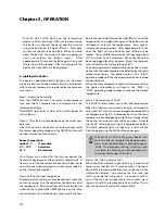
Step 1: Filling fuel

• Do not fill the removable tank in the living

room, but in a more suitable place (there
can always be some spillage).

• Do not refuel the heater while in operation

or still hot.

Follow the procedure below:

[1] Make sure that the heater is switched off.

[2] Open the tank lid and lift the removable tank out of

the heater.

Note: Some drops may leak from the tank. Put down
the removable tank (cap pointing upwards) and
screw off the fuel cap using the fuel cap cover.

[3] Take the manual fuel pump and insert the smooth,

most rigid tube into the jerry can.  Make sure that it
is in a higher position than the removable tank.
Insert the ribbed hose into the opening of the
removable tank.

[4] Lock the switch button on top of the pump (turn

clockwise).

[5] Squeeze the pump a few times, until fuel starts

flowing into the removable tank.  As soon as this
happens, there is no need to press any longer.

[6] Check the removable tank fuel gauge while filling

the tank.  Stop filling by loosening the switch
button on top of the pump (turn anti-clockwise),
once the gauge indicates that the tank is full.  Never
overfill the tank, especially not when the fuel is very
cold (fuel expands when it heats up).

[7] Let the remaining fuel in the pump flow back into

the jerry can and carefully remove the pump.
Carefully screw the fuel cap back on the tank using
the fuel cap cover.  After use, re-store the cover at
the rear of the heater.  Clean off any spilled fuel.

[8] Check whether the fuel cap is straight an tightened

properly.  Reinstall the removable tank in the heater
(cap down).  Close the tank lid.

Step 2: Plug in the heater
Insert the plug into the wall-socket (230 Volts –
AC/50Hz).

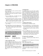
Step 3: Setting the clock
Important: The clock on the heater must always be set
to the correct time.

It is only possible to set the correct time, when the
heater is connected to the mains and not burning.
Use the adjustment buttons to set the time.  First
press either of the two buttons to switch on the

40

Chapter 2, OPERATION

empty

full

Summary of Contents for Laser FF 30

Page 1: ...Laser FF 30 2 24 46 68 MANUEL D UTILISATION OPERATING INSTRUCTIONS GEBRUIKSAANWIJZING KULLANIM KILAVUZU 3 4 1 TR...

Page 2: ...Zibro Yours sincerely PVG International B V Customer Service Department 1 READ THE DIRECTIONS FOR USE FIRST 2 IN CASE OF ANY DOUBT CONTACT YOUR ZIBRO DEALER Dear Sir Madam Congratulations with your pu...

Page 3: ...SUMMARY 25 Chapter 1 INSTALLATION Chapter 2 OPERATION Chapter 3 ERROR MASSAGES Chapter 4 WARRANTY PROVISIONS...

Page 4: ...re you leave or go sleeping Unplug the heater as well when you go away for a longer period of time e g holidays 5 Store and move fuel only in suitable tanks and jerrycans 6 Make sure that the fuel is...

Page 5: ...he manner stipulated in the instructions in the manual Recommended tool kit 1 Crosshead screwdriver 2 Steel tape measure 3 Felt tip pen or pencil 4 Cement for exterior use 5 Electric drill clockwise a...

Page 6: ...the installation kit from the packaging C Remove the heater from the packaging D Remove the plastic bag containing the parts E Remove the exhaust pipe from the bottom of the box F Check that all parts...

Page 7: ...l obstruction 45 cm or more 20 cm or more Snow covered surface or ground Important The gap with the ground must be enlarged in areas subject to heavy snowfall Important A windbreaker may be necessary...

Page 8: ...these are the dimensions and locations of the holes for the fuel pipe and exhaust pipe Do not remove any components from the heater Always contact your dealer if repairs are required If the electricit...

Page 9: ...he following list of standard installation parts is sup plied with your heater It may be necessary to order extra parts from your Zibro dealer if other installation methods are required Wall hooks 2 s...

Page 10: ...Chapter 1 INSTALLATION 32 Flexible air hose 1 Hose clip 2 Manual fuel pump 1 Fuel cap cover 1...

Page 11: ...r can be levelled by means of adjustable legs This can be checked with the plumb line 2 Drill the hole for the exhaust pipe Use a hole saw with a diameter of 70 80 mm see Fig 5 The opening on the inte...

Page 12: ...the inner flue pipe a For wall thickness 230 320mm From inside the room insert the inner flue pipe through the hole Make sure the arrow on the inner flue pipe is pointing up Secure the inner flue pipe...

Page 13: ...ose to the inlet of the exhaust pipe Fasten the right angled air hose onto the inlet with a hose clip Seal the inlets and outlets that are not being used with the caps supplied Check that the caps are...

Page 14: ...ight angled exhaust pipe bend and extension pipe Attach the right angled exhaust bend to the outlet by sliding the pipe lock into the outlet clip See Fig 12 Fig 12 Pipe lock 5 Move the heater into pos...

Page 15: ...hat the airflow to the air circulation ventilator is not obstructed Inspect the interior of the building to ensure that the area immediately adjacent to the heater is free of fuel and objects that may...

Page 16: ...er system All specified operating procedures must be carried out in the order in which they are described 2 Laser FF 30 heater specifications Nominal yield as applied to petroleum heaters 92 7 Power c...

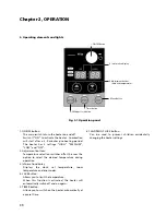
Page 17: ...temperature room temperature and error codes 4 SAVE button Allows you to limit the temperature When this function is activated the heater will automatically switch off and on again 5 TIMER button All...

Page 18: ...longer 6 Check the removable tank fuel gauge while filling the tank Stop filling by loosening the switch button on top of the pump turn anti clockwise once the gauge indicates that the tank is full Ne...

Page 19: ...d the button on the left Ghour to lower the temperature Press once to increase the value one step After approximately 10 sec onds the light will stop blinking and setting will be locked The available...

Page 20: ...m air flowing out of the heater 8 Childproof lock The childproof lock can be used to prevent children accidentally changing the heater settings When the heater is burning and the childproof lock is on...

Page 21: ...own against a hard surface Never clean it with water 3 Reinstall the fuel filter into the heater We recommend that you remove dust and stains in time with a damp cloth because otherwise these may caus...

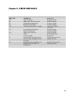
Page 22: ...n the air filter and remove dust E 13 Burner thermistor malfunction Contact your dealer Excess fuel in the burner Contact your dealer E 22 Ignition failure three times Contact your dealer No fuel Refi...

Page 23: ...arranty shall not apply to damages caused by actions not in compliance with the Directions for Use neglect and the use of an incorrect type of fuel or fuel past its use by date The use of incorret fue...

Page 24: ...Finland Oy Piispantilankuja 6C 02240 ESPOO tel 358 9 4390 030 fax 358 9 4390 0320 email appliance appliance group com F FI IN N 4 UNITED KINGDOM Scott Brothers Ltd The Old Barn Holly House Estate Cra...

Reviews: