59
4
b.3 elecTrIcal connecTIon
Familiarize yourself with the safety instructions as mentioned in chapter A.
The electrical connection must be carried out by qualified electrical engineers,
using the supplied cable and plug. Make sure to use a socket which can take the
load factor and voltage as indicated on the technical data table (see chapter H).
Make sure there is an efficient grounding which is in compliance with the standards
in force.
For safety during maintenance it is advised to install a single pole isolating
switch to enable the assurance of a complete disconnection of electricity.
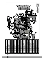
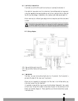
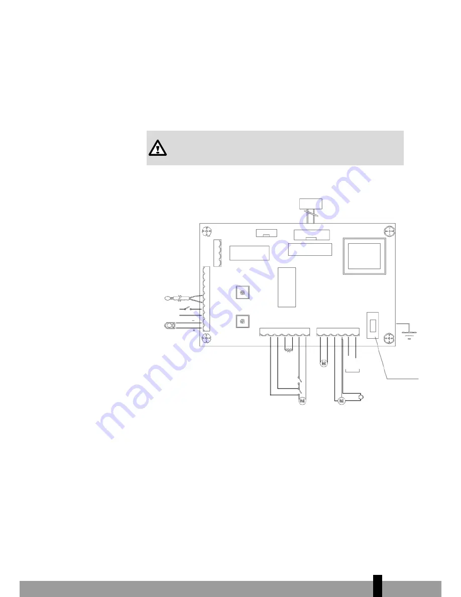
b.3.1 Wiring diagram
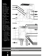
ALP = General safety pressure switch
ALT = General safety thermostat (manual reset)
Diagram 1
Console
Flat cable
Serial tap
Display tap
Microprocessor
Clock module
Starting relay
Environment feeler
External thermostat
Fumes Thermocouple
Blue
Red
Fumes extractor
Condenser
Fuse+4A 5X20 “F”
White
Orange
Grey
Black
White
Brown
Blue
Brown/Black/Blue
Blue
Red
Neutral
Phase
230VCA
Brown
Blue
Starting resistance
Tangential fan
Cochlea
ALT
ALP
b.4 ThermosTaT
The stove can work semi-automatically due to a thermostat. The thermostat is
placed at the back of the stove (see T in picture 2).
Make sure the temperature measurement of the stove is not influenced by any
other heat source than the stove itself.
It is possible to connect the stove to any kind of external thermostat. Use a cable
of 2x0.5 mm². Connect the cables to the relevant points at the electronic circuit
board, see electrical diagram 1. These operations must be carried out by a specia-
lised technician.
Summary of Contents for TOSCA
Page 17: ...17 2...
Page 34: ...34 6...
Page 50: ...50 3...
Page 66: ...66 4...
Page 83: ...83...
Page 85: ...85...
Page 101: ...101 1...
Page 103: ...103 1...
Page 118: ...118...


