Mainboard User's Manual
Page 19
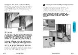
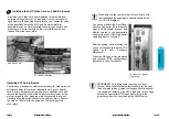
ATX Power Connector.
ATX Power Supply Connector (20-pin ATXPWR)
The single 20-pin connector (B in diagram) incorporates
st5V and +12V, with 3n optional 3.3V ani soft-on/off
signals. With a power supply that supports remote power
on/off, the mainboard can turn off the system power through
the software control, such as the shutdown in Windows 95
Start Menu. The BI0S system will turn the system power off
when it receives the proper APM command from the OS.
APM must be enabled in the BI0S and OS systems in order
for the soft-off feature is to work properly.
Page 18
Mainboard User's Manual
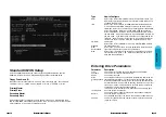
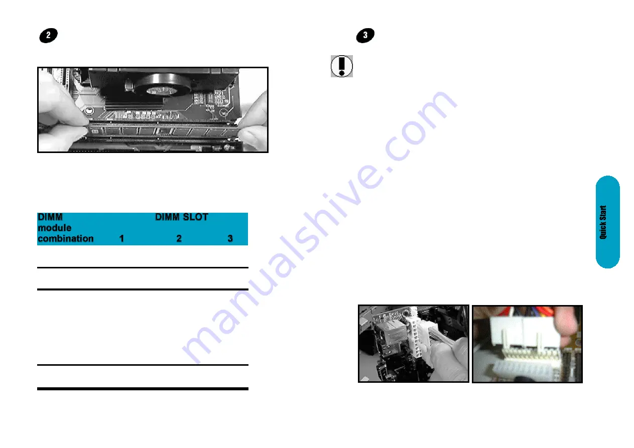
After you have set the memory firmly into its slot snap the
white chip holders up to lock in the memory chip. The chart
below will help you determine what slot to use for the
memory configuration you want.
The following table for mainboards with
WHITE DIMM 3
Only
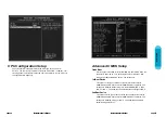
Attaching the power supply ribbon cable
IMPORTANT: Ribbon cables should always be connected
with the red stripe on the Pin 1 side of the connector.
The four corners of the connector's are labeled on the
motherboard. Pin 1 is the side closest to the power
connector on hard drives and floppy drives.
One (1)
S
-
-
Single Bank
Two (2)
S
S
-
Single Bank
Three (3)
S
S
S
Single Bank
Two (2)
S
S
D
Single Bank
+
S
D
S
One (1)
Double Bank
D
S
S
Two (2)
D
D
-
Double Bank
S= Single Bank DIMM module D= Double Bank DIMM module
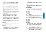
Installing the memory
Memory is installed in DIMM Sockets 1-3 (F in diagram)
as follows, using the chart on the following page.
AT Power Connector.
A 12-Pin power supplies provide two plugs incorporates
standard ñ5V and ñ12V, each containing six wires, two of
which are black. Orient the connectors so that the black
wires are together.
ATX Power Connector
AT Power Connector


