Mainboard User's Manual
Page 21
Page 20
Mainboard User's Manual
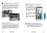
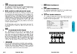
FLoppy Disk Drive Connector (34-pin FLOPPY).
This is a 34-pin connector that supports the provided floppy
drive ribbon cable, After connecting the single end to the
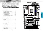
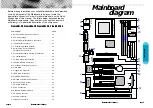
on-board “FLOPPY” connector, (O in diagram) connect the
remaining plugs on the other end to the corresponding
floppy drives.
IDE Connector.
The (2) on-board IDE connector's (P in diagram)support the
provIded 40-pin IDE hard disk ribbon cable. After connecting
the single end to the mainboard, connect the (2) remaining
plugs at the other end of your hard disk(s). If you install (2)
hard disks, you must configure the (2) drives by setting its
jumpers according to the documentation of your hard disk.
Also, you may connect the (2) hard disk drives so that both
become Masters, using one ribbon cable on the primary ID-
connector. and the other on the secondary IDE connector.
NOTE: For the flat ribbon cable connection, please make
sure that the pin 1 of the ribbon cable (the red wire side of
the cable) is correctly connected to the on-board connector's
pin 1 as shown on the “diagram the mainboard”.
Floppy connection
IDE connection
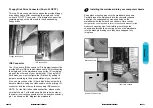
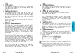
Installing the mainboard into your computer chassis
Snap black mounting pins onto the mainboard as shown.
Carefully insert the mainboard into the computer chassis
and align the corresponding mounting holes on the
mainboard with the holes on you chassis.
While chassis
design varies you may need to refer to the chassis manual for the
mainboard mounting area.
Insert white pins through the
chassis and through the mounting holes on the mainboard
into the black pin making sure they have snapped fully
into place.
Black mount pin
Insert into chassis
Insert White mount pin


