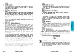
a
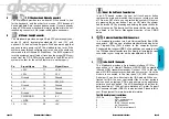
AT Keyboard Connector
The Mainboard provides a on-board AT keyboard
connector.
b
AT Power Connector
A 12-Pin power supplies provide two plugs incorpo
rates st5V and +12V, each containing six
wires, two of which are black. Orient the connectors so
that the black wires are together.
Pin
Signal Name
Pin
Signal Name
1
Power Good Signal
7
Ground
2
+5V
8
Ground
3
+12V
9
-5V
4
-12V
10
+5V
5
Ground
11
+5V
6
Ground
12
+5V
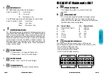
e
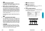
Integrated Function Connector
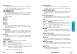
The total of two USB device connectors, a PS/2 mouse,
and an Infrared devices are all allocated at this connector (JP2).
· Pin1 to Pin5 for USB1 connector
· Pin11 to Pin15 for USB2 connector
· Pin6 to Pin10 for PS/2 connector
· Pin16 to Pin20 InfraRed connector
IR
USB 1
1
11
20
USB 2
10
PS/2 Mouse
Mainboard User's Manual
Page 53
FOR BABY AT Mainboards ONLY
U
Audio Connectors
The
ATX
Mainboard provides Audio headers.
Audio Connectors S1 : Line Output
S2 : Line Input
S3 : Microphone Input
The
AT
Mainboard provides Audio header for Audio Cable.
Audio Connectors Black : Line Output
Green : Line Input
Black : Microphone Input
W
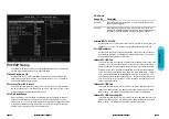
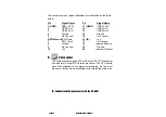
GL520SM Hardware Monitor
The Mainboard provides sophisticated hardware monitoring via
the on-board GL520SM integrated circuit. The GL520SM can be
used to monitor temperatures, power supply voltages, and fan
speeds and will generate interrupts and audible tones that allow
the system speaker to sound an alarm if it detects an abnormal
system situation. Through the SMBus software interface, the
host can program the temperature trip points and query the
GL520SM about system interrupt status, current temperature,
voltage, and fan speed.
X
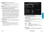
CD Audio Connector
CD Audio Input ( 1,3:Ground,2:Right,4:Left )
CD Audio input ( 1:Left,2,3:Ground,4:Right )
Y
Auxiliary Connector
Auxiliary input ( 1:Left,2,3:Ground,4:Right )
Z
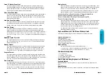
Telephony Connector
Telephony input( 1:Phone,2,3:Ground,4:Mono)
Page 52
Mainboard User's Manual


