background image

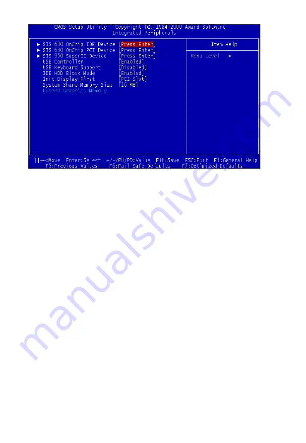
Integrated Peripherals

SIS 630 OnChip IDE Device

This submenu allows you to modify the onboard IDE channel 0 & 1 functions.

Internal PCI / IDE

This option allows you enable/disable onboard IDE channels.

IDE Primary/Secondary Master/Slave PIO

The  four  IDE  PIO  (Programmed  Input/Output)  fields  let  you  set  a  PIO 

mode (0-4) for each of the four IDE devices that the onboard IDE interface 

supports. Modes 0 through 4 provide successively enhanced performance. 

In  Auto  mode,  the  system  automatically  determines  the  best  mode  for 

each device.

Page 28

 Mainboard User's Manual

Summary of Contents for V630E

Page 1: ...USER S MANUAL More compatible more functional and more competitive Excellent quality and faster response Supporting Socket 370 Processors UDMA33 66 PC100 133 SDRAM Quality Performance Mainboards ...

Page 2: ...efit without intent to infringe VIA is a registered trademark of VIA Technologies Incorporated IBM IBM PC IBM PC AT PC DOS OS 2 and OS 2 WARP are registered trademarks of International Business Machines Corporation Ms DOS Windows Windows NT Windows 98 Windows 95 and Windows 2000 are registered trademarks of Microsoft Corporation AMI BIOS is a product of American Megatrends Inc AWARD BIOS is a prod...

Page 3: ...ling the Memory 13 Attaching ATX Power Connector 14 Floppy Disk Drive Connector 15 IDE Device Connector 16 Mounting Mainboard to chassis 17 Installing PCI Add on Boards 18 BIOS Setup 20 Glossary 37 LAN Installation Guide 45 CD Driver Software Installation Guide 46 Norton AntiVirus OEM Version Setup Guide 47 INSTANT ON Guide 49 Mainboard User s Manual Page 3 Table of Contents ...

Page 4: ......

Page 5: ...drives or CD ROM s It s I O controller integrates floppy drive interface two FIFO serial ports one parallel port and Consumer Infra Red compatible interface SIS 630E Chipset supports SOCKET 370 Processors with 100 100 133MHz Front side Bus Supports 100 133MHz PC100 133 SDRAM DIMM Two DIMM slots support up to 1GB Memory Capacity Four USB ports support USB Devices WAKEUP LINK Header supports Wake On...

Page 6: ...d circuit assemblies rough edges and corners and hot components Your Location Requirements Are A sturdy level surface for placement Space allowance around mainboard A stable environment with no abrupt temperature or humidity changes No exposure to chemicals or direct sunlight Line voltage and frequency not varying more than or 10 from the value stated on the package or nameplate located on the bac...

Page 7: ...he representative for part replacement Baby ATX Box Standard Package 1 Mainboard 2 Driver CD with Norton AntiVirus 2001 OEM Version 3 User Guide 4 IDE Hard Drive Ribbon Cable 5 Floppy Drive Ribbon Cable 6 USB Cable for onboard USB Header Optional 7 Audio Game Cable 8 LAN Module Optional 9 VGA Cable 10 COM X LPT Cable 11 PS 2 Cable Installation Mainboard User s Manual Page 7 ...

Page 8: ...2 Mouse Header 37 B ATX Power Supply Connector 37 b AT Power Supply Connector 38 C Universal Serial Bus USB Header 38 D Serial COM 1 2 Headers 39 E Infra Red IR Connector 39 F Memory Module Sockets 39 G Parallel Port Connector 40 I Lithium Battery 40 J PCI Add In Board Connector 40 M Front Panel Function Connector 40 N Flash BIOS 41 O Floppy Drive Connector 41 P IDE Device Connector 41 Q WAKEUP LI...

Page 9: ...Mainboard User s Manual Page 9 Mainboard Diagram Mainboard Diagram ...

Page 10: ...Page 10 Mainboard User s Manual Clear CMOS Set the Jumper JP4 to 1 2 to clear CMOS Remember Please set it back to normal 2 3 after clear CMOS ...

Page 11: ... static free before you begin this section Page 11 Mainboard User s Manual The Mainboard provides a 370 pins Socket The CPU should have a fan attached to prevent overheating If a fan is not present user should purchase a fan prior to turning on the system The recommended heatsinks for the Socket 370 processor are those with three pin fans that can be connected to the fan connectors on the Mainboar...

Page 12: ...ON Be sure that sufficient air circulation must be available across the processor s heatsink Without sufficient circulation the processor could overheat and damage both the processor and the mainboard You may install an auxiliary fan if necessary Mainboard User s Manual Page 12 ...

Page 13: ...ge 13 Mainboard User s Manual After you have set the DIMM firmly into its socket snap the white chip holders up to lock in the DIMM Installing the Memory Memory is installed in DIMM Sockets 1 2 F in diagram as follows ...

Page 14: ...rn the system power off when it receives the proper APM command from the OS APM must be enabled in the BIOS and OS systems in order for the soft off feature to work properly For AT power supply short all the jumper from J2 1 2 J2 3 4 J2 5 6 For ATX power supply open all the jumper J2 1 2 J2 3 4 J2 5 6 Attaching the power supply ribbon cable IMPORTANT Ribbon cables should always be connected with t...

Page 15: ...or 34 pin FLOPPY This is a 34 pin connector that supports the provided floppy drive ribbon cable After connecting the single end to the on board FLOPPY connector O in diagram connect the remaining plugs on the other end to the corresponding floppy drives Floppy connection ...

Page 16: ...ust configure the drives by setting its jumpers according to the documentation of your hard disk Also you may connect the hard disk drives so that both become Masters using one ribbon cable on the primary IDE connector and the other on the secondary IDE connector NOTE For the flat ribbon cable connection please make sure that the pin 1 of the ribbon cable the red wire side of the cable is correctl...

Page 17: ...and align the corresponding mounting holes on the mainboard with the holes on your chassis While chassis design varies you may need to refer to the chassis manual for the mainboard mounting area Insert white pins through the chassis and through the mounting holes on the mainboard into the black pin making sure they are snapped fully into place Black mounting pin Insert into chassis Insert White mo...

Page 18: ... settings that may be required to set up your specific card Set any necessary jumpers on your expansion card and remove the cover plate on your computer case at the slot you intend to use Keep the plate for possible future use Carefully align the card s connector and press firmly Secure the card on the slot with the screw you removed from the cover plate ...

Page 19: ...BIOS Setup ...

Page 20: ...drive Monitor type and if keyboard is installed Sets Typematic Rate and Delay Above 1 MB Memory Test Memory Test Tick Sound Hit Del Message Display System Boot Up Sequence and many others Sets chipset specific options and features Controls I O Controller related options Controls power savings options Sets options related to PCI bus and Plug and Play options Display CPU or System Temperature Fan Sp...

Page 21: ...re described below Date mm dd yy Setting for the system Date Time hh mm ss Setting for the system Time IDE Primary Master IDE Primary Slave IDE Secondary Master IDE Secondary Slave Floppy Drive A and B Move the cursor to these fields and select the floppy type The setting are 360 KB 5 1 4 inch 1 2 MB 5 1 4 inch 720 KB 3 1 2 inch 1 44MB 3 1 2 inch or 2 88 MB 3 1 2 inch ...

Page 22: ...be stopped for any error that may be detected All errors Whenever the BIOS detects a non fatal error the system will be stopped and you will be prompted All But Keyboard The system boot will not stop for a keyboard error it will stop for all other errors All But Diskette The system boot will not stop for a disk error it will stop for all other errors All But Disk Key The system boot will not stop ...

Page 23: ...uring system boot up The default value is Disabled CPU Internal Cache This category enables or disables the CPU internal cache to speed up memory access The default value is Enabled External Cache This category enables or disables the secondary level L2 cache to speed up memory access The default value is Enabled CPU L2 Cache ECC Checking This category enables or disables the CPU L2 cache ECC Chec...

Page 24: ...abled When this function enables the system will assign the Drive A as Drive B and vice versa Boot Up Floppy Seek The default setting is Enabled so that the BIOS will search for floppy disk drive during boot up If disabled BIOS will not search for the type of floppy disk drive by track number Note that there will be no warning message if the drive installed is 360K Boot Up NumLock Status It determ...

Page 25: ...ust be entered at the prompt The default setting is Setup OS Select For DRAM 64MB Some of the OS 2 application access the memory in different mode Enable this option to allow the system use another mode to access the main memory for OS 2 applications Report No Floppy Disk For Windows 95 The system will report floppy disk status to Windows 95 if setting is Yes VIDEO BIOS Shadow The system BIOS is a...

Page 26: ... on the system with loading the Load Optimized Defaults System BIOS Cacheable Selecting Enabled allows caching of the system BIOS ROM at F0000h FFFFFh resulting in better system performance However if any program writes to this memory area a system error may result The choice Enabled Disabled Video RAM Cacheable Select Enabled allows caching of the video RAM resulting in better system performance ...

Page 27: ...ption allows you to enable disable the 128x4 Post Write Buffer Concurrent Function MEM This option allows you to optimize the utilization of memory bus for both CPU access memory cycles and PCI masters access memory cycles Concurrent Function PCI This option allows you to enable both CPU access PCI bus cycle and PCI masters access memory cycles concurrently CPU Pipeline Control This option enables...

Page 28: ...onboard IDE channels IDE Primary Secondary Master Slave PIO The four IDE PIO Programmed Input Output fields let you set a PIO mode 0 4 for each of the four IDE devices that the onboard IDE interface supports Modes 0 through 4 provide successively enhanced performance In Auto mode the system automatically determines the best mode for each device Page 28 Mainboard User s Manual ...

Page 29: ...his option enables the onboard AMR S W modem function SIS 900 10 100M Ethernet This option enables the onboard integrated Ethernet controller SIS 900 MAC Address Input This option defines the LAN MAC Address of the system when the onboard integrated Ethernet controller is enabled SIS 950 Super IO Device This submenu allows you to modify the onboard I O function Installation details please refer to...

Page 30: ...onboard parallel printer port Normal EPP Extended Parallel Port ECP Extended Capabilities Port ECP EPP PC AT parallel port Bidirectional port Fast buffered port Fast buffered bidirectional port Select Normal unless you are certain your hardware and software both support these modes Choices are SPP EPP ECP ECP EPP ECP Mode Use DMA Select a DMA channel for the port Choices are 3 1 Parallel Port EPP ...

Page 31: ... The choice S1 POS S3 STR Video OFF Option When enabled this feature allows the VGA adapter to operate in a power saving mode Always On Monitor will remain on during power saving modes Suspend Off Monitor blanked when the system enters the Suspend mode All Modes Off Monitor blanked when the system enters any power saving mode Susp stby Off Monitor blanked when the system enters either suspend or s...

Page 32: ... you to enable the EXTSMT switch MODEM Use IRQ This determines the IRQ in which the MODEM can use The choice 3 4 5 7 9 10 11 NA HDD Off After This option sets the HDD power down after certain event Power Button Override Pressing the power button for more than 4 seconds forces the system to enter the Soft Off state when the system hung The choice Delay 4 Sec Instant Off PM Wake Up Events Wake Up ar...

Page 33: ... an incoming call on the modem or Lan awakens the system from a soft off state RTC Alarm Resume When Enabled you can set the date and time at which the RTC real time clock alarm awakens the system from Suspend mode These options specify the IRQ priority for PCI devices installed in the PCI expansion slots The setting is Auto When set On activity will neither prevent the system from going into a po...

Page 34: ...Enabled to reset Extended System Configuration Data ESCD when you exit Setup The choice Enabled Disabled Resources Controlled By The Award Plug and Play BIOS has the capacity to automatically configure all of the boot and Plug and Play compatible devices However this capability means absolutely nothing unless you are using a Plug and Play operating system such as Windows98 The choice Auto Manual P...

Page 35: ...t DIMM PCI Clk Options Enabled Disabled Spread Spectrum Options Enabled Disabled CPU HOST SDRAM PCI Clock This option sets the frequencies of CPU DIMM and PCI clocks CPU Clock Ratio Jumpless This option sets the Clock Ratio between CPU Internal frequency and CPU External Frequency ...

Page 36: ...Glossary ...

Page 37: ... on off the mainboard can turn off the system power through software control such as the shutdown command in the Windows 95 Start Menu The BIOS system will turn the system power off when it receives the proper APM command from the OS APM must be enabled in the BIOS and OS systems in order to set the soft off feature working properly Pin Signal Name Pin Signal Name 1 3 3V 11 3 3V 2 3 3V 12 12V 3 Gr...

Page 38: ...wer Management section of the CMOS setup b AT Power Supply Connector The Mainboard also provides a 12 pin AT power supply connector which incorporates standard 5V 12V Pin Signal Name Pin Signal Name 1 5V 7 Ground 2 5V 8 Ground 3 12V 9 5V 4 5V 10 5V 5 Ground 11 5V 6 Ground 12 5V C Universal Serial Bus USB Header The Mainboard provides four 4 pin Universal Serial Bus USB Header USB is a new interfac...

Page 39: ...gured for IrDA the user can transfer files to or from portable devices such as laptops PDA s and printers using application software such as LapLink The IrDA specification provides for data transfers at 115 kbps from a distance of 1 meter Support for Consumer infrared ASK IR is also included Please refer to your IR equipment for more detailed information The header pin out is as follows Pin Signal...

Page 40: ...of explosion if battery is incorrectly replaced Therefore if you have any difficulties please consult the technical personnel J PCI Add In Board Connector The Mainboard provides 3 PCI Connectors for the PCI cards M Front Panel Function Connector The Mainboard integrates all system front panel functions into a single on board connector These include connections for the following features Function C...

Page 41: ...ra DMA 33 66 devices The system BIOS supports automatic detection of the IDE device data transfer rate and translation between different kinds of device modes such as Logical Block Addressing LBA Extended Cylinder Sector Head ECSH translation modes and ATAPI e g CD ROM devices on both IDE interfaces The two on board IDE connectors support the provided 40 80 pin IDE hard disk ribbon cables After co...

Page 42: ...in LAN Connector for the Onboard 100Mbps PCI LAN r Audio Modem Riser AMR Connector The Mainboard provides a AMR Connector for the AMR cards S CPU Socket The Mainboard provides a 370 pin Socket 370 CPU Socket for Intel PIII FCPGA Celeron PPGA Processor The CPU should have a fan attached to it to prevent overheat If a fan is not present a fan should be installed prior to turning the system on Page 4...

Page 43: ... 2 12V 3 Ground CAUTION Be sure that sufficient air circulation is available across the processor s heatsink by regularly checking that your CPU fan is working Without sufficient circulation the processor could overheat and damage both the processor and the mainboard You may install an auxiliary fan if necessary U Game Audio Connector The Mainboard provides Audio headers Audio Connectors L Out Lin...

Page 44: ...tor for the Integrated Graphics Controller X CD Audio Connector CD Audio input Right Ground Ground Left Y Auxiliary Connector Auxiliary input Right Ground Ground Left y Video Connector Video input Left Ground Ground Right Page 44 Mainboard User s Manual ...

Page 45: ...s if the CMOS is occassionally lost Please follow the following steps to restore the LAN MAC Address 1 Boot up the system and enter CMOS Setup 2 Enter the SIS630 Onchip PCI Device of Integrated Peripherals Setup 3 Choose SIS 900 MAC Address Input and enter the default MAC address Default MAC Address 00 E0 06 XX XX XX 4 Exist and save the CMOS settings 5 Follows the installation procedures of the d...

Page 46: ...oot up the Operating System Windows 95 98 NT 2000 2 Put the CD Disc into the CD ROM Drive and wait for Autorun 3 Select V630E and click your Operating System Type 4 Follow the instructions and install suitable drivers Mainboard User s Manual Page 46 ...

Page 47: ...irus OEM Version Setup Guide Step 1 Load the Driver CD in CDROM and find the Norton AntiVirus 2001 Install Option Step 2 When CD finishes loading press Install Norton AntiVirus to install the software Mainboard User s Manual Page 47 ...

Page 48: ...Step 3 Follow the installation procedures on screen Step 4 Select Yes and press Finish button to reboot computer Page 48 Mainboard User s Manual ...

Page 49: ... recognize various wake up triggers or signals respectively INSTANT ON function Installation Please follow the steps to complete the INSTANT ON function installation There are two ways 1 Setup with Windows 98 CD A Insert the Windows 98 CD into your CD ROM drive select Start and then Run B Type without quotes D setup p j in the window provided Hit the enter key or click OK C After setup completes r...

Page 50: ...em C Select the Device Manager tab and then the System Devices item Double click the Plug and Play BIOS item or select Properties 2 Update from Windows98 Advance Power Management APM mode If your Windows 98 system is in APM mode please follow the steps to update your system to ACPI mode Page 50 Mainboard User s Manual ...

Page 51: ...pdate Device Driver Wizard will appear Press the Next button F In the Update Device Driver Wizard window select the Display a list of all the drivers in a specific location so you can select the driver you want Then press the Next button Mainboard User s Manual Page 51 ...

Page 52: ...r Warning will show up and ask Are you sure you want to use this driver Select the Yes button I Update Device Driver Wizard will show up again Select the Next button and start copying files to the system J When complete press the Finish button K Restart your computer Your system will start up using the ACPI mode Page 52 Mainboard User s Manual ...

Page 53: ...BIOS Setup Select the item POWER MANAGEMENT SETUP then select Enable in Suspend to RAM option Remember to save the settings by pressing ESC and choose the SAVE EXIT SETUP option The installation of INSTANT ON is completed You can use this function in Windows 98 Mainboard User s Manual Page 53 ...

Page 54: ...tem into Stand by mode There are two ways 1 Choose the Stand by item in the Shut Down Windows area B Choose the Stand by item and Click OK A Press the Start button and then select Shut Down Page 54 Mainboard User s Manual ...

Page 55: ...INSTANT ON GUIDE 2 Set the system power on button to initiate sleep mode A Double click My Computer and then Control Panel B Double click the Power Management item Mainboard User s Manual Page 55 ...

Page 56: ...en you want to enter sleep mode just press the Power on button How to recover from the sleep mode There are four ways to wake up the system 1 Press the Power On button 2 Use the Keyboard Power On function 3 Use the Modem Lan Resume function 4 Use the Resume by Alarm function Page 56 Mainboard User s Manual ...

Page 57: ...ON GUIDE Notice to INSTANT ON users 1 ATX power supply requirement comply with the ATX 2 01 provide more than 720 mA 5V Stand By current 2 SDRAM requirement PC 100 133 compliant Mainboard User s Manual Page 57 ...

Reviews: