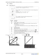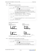
Lmt E1 min
Both values for E1 (
“
E1 min
”
and
“
E1 max
”
) can be set independent of each other and
act on a relay together if correspondingly programmed. If a function is activated or if a
relay is allocated, both settings (
“
min
”
and
“
max
”
) are initially at
“
OFF
”
.
Work can be carried out with one as well as with both limit indicators.
The same setting applies to
“
E2 Min.
”
and
“
E2 Max.
”
, described below for
“
E1
”
.
Undercutting the signal (
“
E1 Min
”
).
If the signal undercuts the set value
“
E1 min
”
, this is reported until the set value (plus
adjustable hysteresis) has been exceeded once again.
Exceeding the signal (
“
E1 max
”
).
If the signal exceeds the set value
“
E1 max
”
, this is reported until the set value (minus
hysteresis) has been undercut once again.
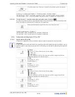
Lmt E1 max.
Lmt E1 Hyst.
E1 Hysteresis
Hysteresis adjustment in the unit of measure of the programmed input signal.
Lmt E1 Del.
E1 Delay
Time delay exceeding
“
Modulation max.
”
up to indication by relay and alarm symbol.
Setting range: 0 - 120 sec.
Factory setting: 2 sec.
Information
Always adjust the value for the maximum input signal higher than the value for the minimum input
signal!
E1 Max. > E1 Min.
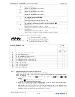
Example for a limit indication of default signal or sensor signal to
“
Analog In 1
”
50 %
Analog IN
0
1
100 %
1
11.05.2007
v_grenzwert_signal_k1_1.vsd
Settings:
- E1 Max.: 80 %
- E1 Min.: OFF
- switching hysteresis 5 % (from
100 %)
50 %
Analog IN
0
1
100 %
2
11.05.2007
v_grenzwert_signal_k1_2.vsd
Settings:
- E1 Min.: 20 %
- E1 Max.: OFF
- switching hysteresis 5 % (from
100 %)
50 %
Analog IN
0
1
100 %
3
11.05.2007
v_grenzwert_signal_k1_3.vsd
Settings:
- E1 Min.: 20 %
- E1 Max.: 80 %
- switching hysteresis 5 % (from
100 %)
Terminal
“
E1
”
and
“
GND
”
alarm via relay
“
K1
”
(non-inverted) IO Setup
→
K1 function:
|
5 K
|
= limit
indicators
9.11.3
Limit indication depending on (offset) to Setpoint
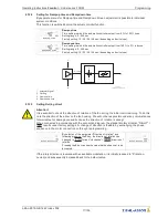
In operating modes as a controller (via
2.01
), two limit indicators can be carried out based on the set
target value (Setpoint) and measured actual value (on E1).
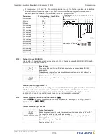
Offset Function
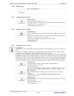
Following functions can be allocated to the limit indication
OFF
no function
1L
Indication with the centralized fault of a programmed relay (IO allocation
function
|
2K
|
) warning symbol in display,
“
AL
”
code in events memory.
2L
Is merely displayed in the events menu as message
“
msg
”
.
In the IO setup, a separate relay can be allocated independent of these settings.
Operating Instructions
Fcontrol
–
model series FXDM
Programming
L-BAL-E072-GB 1642 Index 008
Part.-No.
73/105


