Frequency
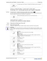
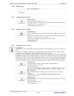
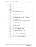
Active brake mode is signaled by a bright triangle in the display.
9.12.8
Boost function
The boost function5is an automatic voltage increase in case of dynamic demands on the control
system. When using the square characteristic, the output voltage is increased to the value of the linear
characteristic with the
“
Boost function
”
switched on. This induces more torque on the motor and the
current therefore does not increase too much when accelerating. Just before reaching the setpoint of
the modulation, the motor voltage corresponding to the square characteristic is switched back to. The
boost process is only activated in case of a suf
fi
ciently large increase in modulation (from approx.
5 %).
In operation with linear characteristic (
“
UF square
”
=
“
OFF
”
) the Boost function is not possible.
Boost function
Boost function
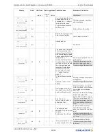
ON: automatic voltage increase switched on
OFF: automatic voltage increase switched off (at factory)
9.12.9
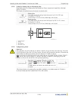
Setting Derating Alarm
The device has integrated active
“
temperature management
”
to protect the device from damage
caused by excessively high interior temperatures.
Derating Alarm
In case of a temperature increase above the set limits (for capacitor temperature and
heat sink temperature
diagnostic menu) the modulation is linearly reduced until the
stated limit temperatures are reached.
To prevent a shut down of the entire system (in this operating mode, allowable for the
controller), no alarm indication occurs during reduced operation until the preset thresh-
old value
“
Derating Alarm
”
is reached.
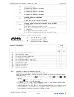
Active temperature management is signaled by a bright triangle in the display.
Derating Alarm
Setting:
Derating Alarm
The factory preset for the
“
Derating Alarm
”
is 5 %.
Setting range: 1...95 % (
1...95 % of the maximal possible frequency)
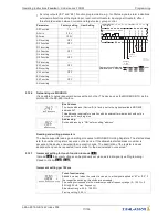
Overload 1
Indication:
Overload1
If the modulation (frequency) of the device only corresponds to the value set in
“
Derating Alarm
”
due to too high an internal temperature, the fault indication
“
Over-
load
”
is displayed.
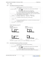
Behaviour of the relays
“
K1
”
and
“
K2
”
in case of factory setting (
IO Setup)
The alarm relay
“
K2
”
drops out, the terminals 21-22 are bridged, the operation relay
“
K1
”
stays pulled up (terminals 11-14 bridged).
Operating Instructions
Fcontrol
–
model series FXDM
Programming
L-BAL-E072-GB 1642 Index 008
Part.-No.
79/105


