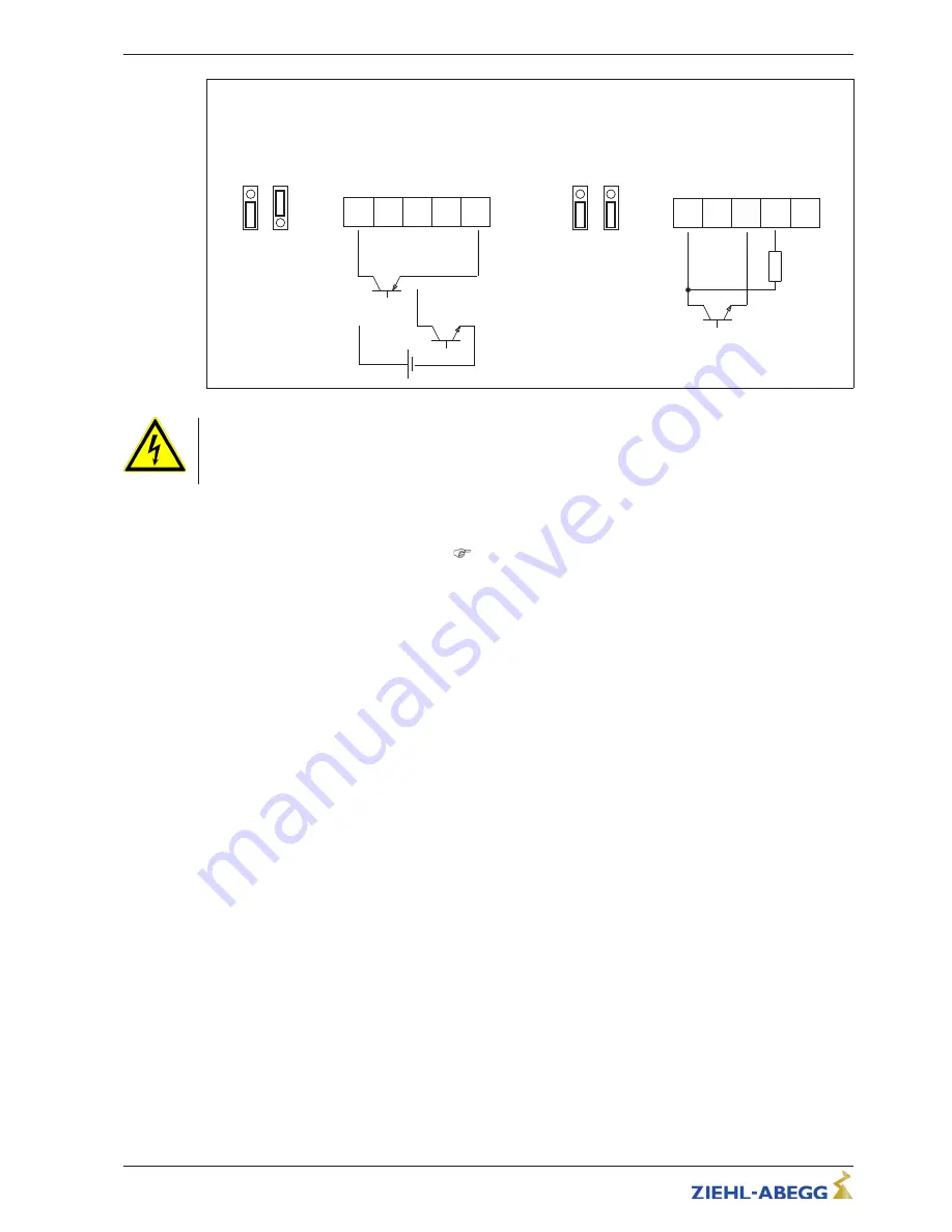
0...100 % PWM
Control via external setting signal PWM
E1,1 E1,2
PWM
E1
D1 GND 10V
An
a
lo
g
I
n
1
1
0
V
D
C
O
u
t
31.01.12
i_jumper_if_basic_pwm.eps
24V
2
4
V
D
C
O
u
t
2
4
V
15...28 V
+
-
G
N
D
E1
E1,1 E1,2
PWM
(10 V)
E1
D1 GND 10V
An
a
lo
g
I
n
1
1
0
V
D
C
O
u
t
24V
2
4
V
D
C
O
u
t
PWM
f = 1...10 kHz
10 kΩ
Danger due to electric current
•
Do not replug the jumper under voltage, observe the safety instructions!
•
Make sure the signal has the correct polarity!
•
Never apply line voltage to analog inputs!
5.8
Output voltage
“
10 V
”
Voltage supply e.g. for speed setting by external potentiometer.
Connection:
“
10 V
”
-
“
GND
”
(max. load
Technical data und connection diagram).
•
It is not permissible to connect voltage outputs of several devices to each other!
•
It is not permissible to connect voltage outputs in the device to each other!
5.9
Voltage supply for external devices (+24V, GND)
A voltage supply is integrated for external devices e.g. a sensor (max. current load see technical
data).
In case of overload or short circuit (24 V
–
GND), the external power supply is shut down (multi-fuse).
The device performs a
“
Reset
”
and continues operation.
•
It is not permissible to connect voltage outputs of several devices to each other!
•
It is not permissible to connect voltage outputs in the device to each other!
Operating Instructions
Icontrol Basic
–
model series FSDM2.6...62
Electrical installation
L-BAL-E160-GB 1701 Index 004
Part.-No.
16/28


