5.10
Digital input
“
D1
”
for enable (device ON / OFF)
Electronic disconnection and Reset after motor fault via
fl
oating contact at terminals
“
D1
”
-
“
24V (input
resistance and voltage range
Technical data)
”
.
Function factory setting for
“
D1
”
:
•
Device
“
ON
”
for closed contact.
•
Device
“
OFF
”
with opened contact.
Activation via
fl
oating contacts, a low voltage of approx. 24 V DC is connected.
Danger due to electric current
•
No disconnection (no potential isolation in accordance with VBG4
§
6) in remote control of the
device!
•
Never apply line voltage to the digital input!
5.11
Relay outputs
“
K1
”
An external fault indicator is available over the potential-free contact of the built-in relays (max. contact
rating
Technical data and connection diagram).
Function factory setting for
“
K1
”
:
•
For operation the relay is energized, connections
“
13
”
and
“
14
”
are bridged. For fault the relay is de-
energized (
Diagnostics / faults).
•
When switching off via enable (D1 = Digital In 1), the relay remains energized.
5.12
Bypass circuit
Please observe the following during bypass switching (controller shunt with mains voltage):
•
Mutual locking of mains contactor and bypass protection.
•
Time delay of at least 1 second during switching.
•
When the contactor is switched off at the inverter output, the
“
enable
”
(ON / OFF) must also be
opened and closed again when it is switched back on. When switching off, wait at least 90 seconds
before switching back on!
•
Never apply line voltage to the inverter output!
5.13
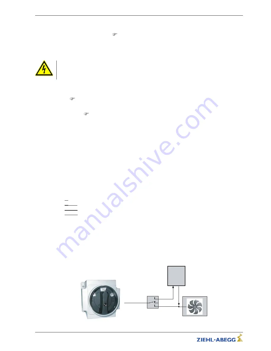
Manual Bypass-Switch type S-D-25 and S-D-50
As accessories are manual main switches with bypass function available.
By switching OFF Frequency inverters necessary waiting period before renewed switching on
amounts minimum 90 seconds!
Switch position
•
|
0
|
= Switch OFF supply line (lockable)
•
|
AUTO
|
= Operation Control
•
|
100 %
|
= Operation Bypass (controller without supply)
Technical data
•
Line voltage max. 690 V, 50/60 Hz
•
Rated current
–
Type S-D-25 Part.-No. 349035: 25 A
–
Type S-D-50 Part.-No. 349040: 50 A
•
Dimensions w x h x d [mm]
–
Type S-D-25: 115 x 115 x 163
–
Type S-D-50: 135 x 135 x 188
•
Protection class IP65
S-D-25
AUTO
0
100 %
3 ~ 400 V
Controller
S-D-25
04.12.2007
v_sd25.vsd
Manual Bypass-Switch type S-D-25 / S-D-50
Operating Instructions
Icontrol Basic
–
model series FSDM2.6...62
Electrical installation
L-BAL-E160-GB 1701 Index 004
Part.-No.
17/28


