background image

9.1.3

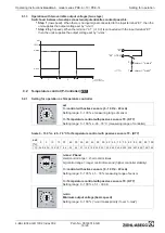
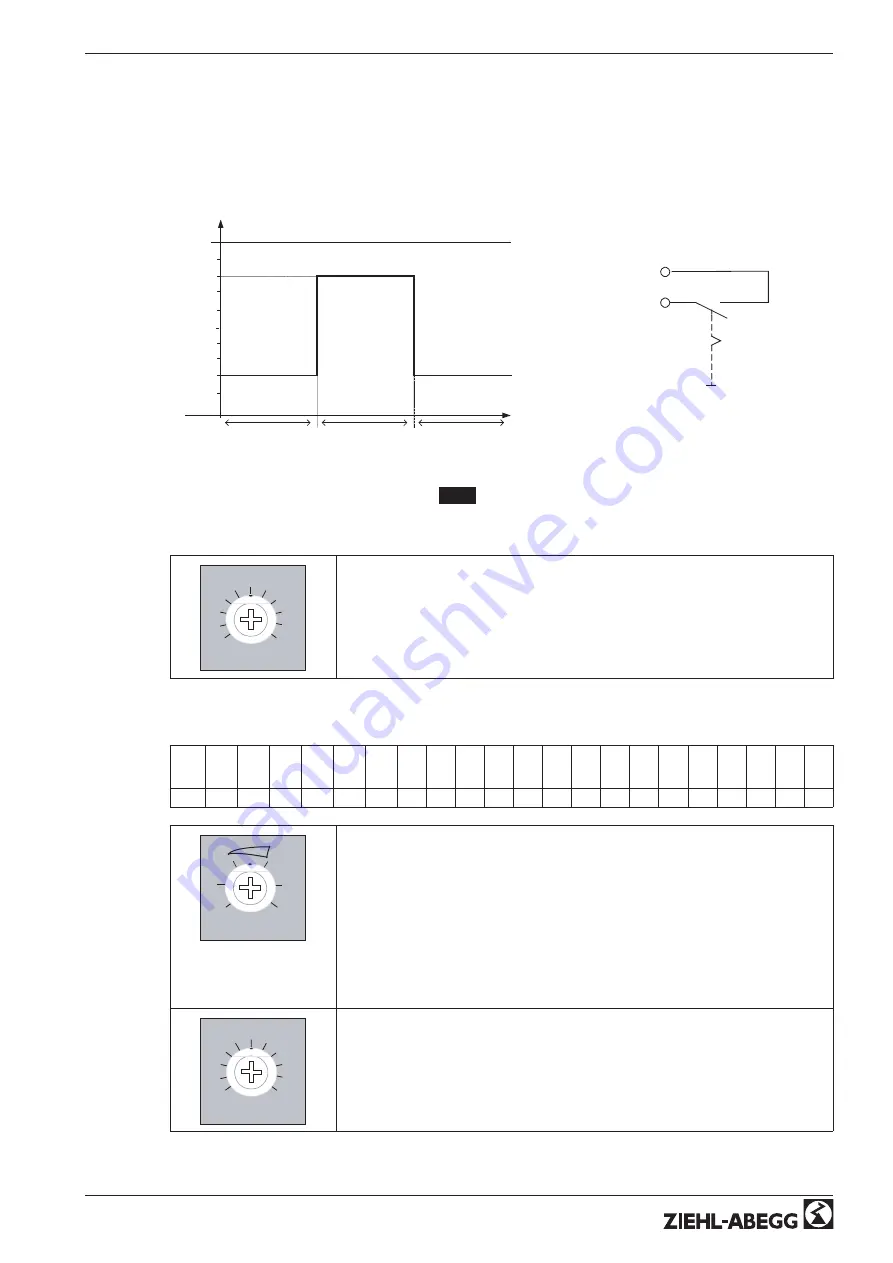
Operation with two variable output voltages (two steps)

Switchover between two steps via external potential-free contact possible.

Step 1

(low speed). When there is no input signal connected to the input terminal

E1

, then the

unit supplies the output voltage set by

n-min

.

Step 2

(high speed). When the terminal

A1

(+10 V) is connected with the input terminal

E1

then the units supplies the output voltage set by

n-max

.

n-min

nM

100 %

1

t

n-max

1

2

05.02.2008

v_diagr_2stufen.VSD

"A1" (+10 V)

"E1"

nMotor 

= "n-max"

nMotor 

= "n-min"

1

2

05.02.2008

v_schalter_2stufen.VSD

9.2 Temperature control (P-Controller)

2.01

9.2.1

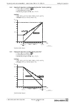
Setting for operation as Temperature controller

28.08.2008
v_set_pke.VSD


%

0


100


R47

set

set

For

control with active sensors (0 - 10 V, 4 - 20 mA)

Setting range: 0 - 100 %

measuring range of sensor

For

Temperature control with passive sensors TF.. (KTY)

Setting range: 0 - 100 %

-26...76

°

C (measuring range of controller)

Scale 0 - 100 %

-26...76

°

C for Temperature control with passive sensors TF.. (KTY)

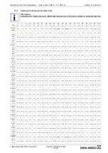
set

[%]

0

5

10 15 20 25 30 35 40 45 50 55 60 65 70 75 80 85 90 95 100

[

°

C] -26.0 -20.9 -15.8 -10.7 -5.6 -0.5 4.6 9.7 14.8 19.9 25.0 30.1 35.2 40.3 45.4 50.5 55.6 60.7 65.8 70.9 76.0

28.08.2008
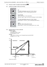
v_nmax_pband_pke.VSD

n-max /

 P-band

R

4

9


%


5

30

n-max

=

Pband

small control range = short control times
big control range = longer control times and (higher controller stability)

For

control with active sensors (0 - 10 V, 4 - 20 mA)

Setting range: 0 - 100 %

5 - 30 % measuring range of sensor

For

Temperature control with passive sensors TF.. (KTY)

Setting range: 0 - 100 %

5.1 - 30.6 K


%

0


100


n-min

R

4

8

28.08.2008
v_nmin_pke.VSD

n-min
Minimum output voltage (basic speed)

Setting range: 0 - 100 % (

n-min

takes priority if over

n-max

)

Operating Instructions

Acontrol

model series PKE-6 /-10 / PKE-14

Setting for operation

L-BAL-E042-GB 1002 Index002

Part.-No. 00163314-GB

16/26

Summary of Contents for Acontrol PKE-6

Page 1: ...ntrol PKE 6 10 PKE 14 P controller and speed controller for variable voltage 1 fans Operating Instructions Software version D1361A from Version 00 L BAL E042 GB 1002 Index 002 Part No 00163314 GB engl...

Page 2: ...uences during commissioning 7 5 Electrical installation 8 5 1 Safety precautions 8 5 2 EMC compatible installation 8 5 2 1 Motor feeder cable 8 5 2 2 Signal cable 8 5 3 Mains connection 8 5 4 Motor co...

Page 3: ...mperature control Heating function 17 9 3 Pressure control condensers P Controller 3 01 18 9 3 1 Setting for operation as Pressure controller 18 9 3 2 Example Pressure control condensers 18 9 3 3 Sett...

Page 4: ...illustrations or drawings provided Ziehl Abegg AG is not liable for damage due to misuse incorrect use improper use or as a consequence of unauthorized repairs or modi cations 1 4 Copyright These oper...

Page 5: ...Also note the instructions of AEL DLG VdS 2 4 Requirements placed on the personnel due diligence Persons entrusted with the planning installation commissioning and maintenance and servicing in connec...

Page 6: ...tractor or owner must also ensure that the electric systems and equipment are operated and maintained in accordance with electro technical regulations The owner is obliged to ensure that the device ar...

Page 7: ...e on a clean and stable base Do not distort during assembly Use the appropriate mounting devices for proper installation of the unit Do not mount equipment on vibrating base When mounted onto lightwei...

Page 8: ...arance or thermal shielding is required 4 3 Outdoor installation Outdoor installation is possible up to 20 C when the controller supply is not switched off Installation must be protected from the effe...

Page 9: ...astic housing parts because there is no potential equalization Never clean electrical equipment with water or similar liquids Information The respective connections are represented in the enclosure of...

Page 10: ...ection is required We cannot under any circumstances accept liability for damage to the motors which do not have the required motor protection It is recommended that every fan is equipped with a separ...

Page 11: ...ted Attention No disconnection isolation when turned off in accordance with VBG4 6 Never apply line voltage to the digital input It is not permissible to connect inputs of several devices to each othe...

Page 12: ...over n max Potentiometer n max Pband Function dependently on selected mode of operation For speed controller 1 01 Maximal output voltage speed limiter Setting range 100 n min 100 output voltage fully...

Page 13: ...tches Attention Setting of jumper and switches not under voltage Observe the safety notices Changed functions become active partly only after renewed switching on the mains voltage E1 Analog In factor...

Page 14: ...tch S1 Position factory setting for all dipswitches OFF DIP Function OFF ON 1 Selection Speed controller P Controller Speed controller P Controller 2 Minimum speed cut off OFF ON 3 Type of Signal 0 10...

Page 15: ...ON OFF approx 2 5 of 100 set value nM 50 100 I Min Min 35 Max 100 20 C S 7 K R 27 C 2 0 K 10 05 2007 v_min_luft_abschalt vsd Minimum speed cut off idealized principle diagram nM Motor speed S Setpoin...

Page 16: ...priority if over n max 28 08 2008 v_nmax_pband_pke VSD n max P band R 4 9 5 30 n max Pband Maximal output voltage speed limiter Setting range 100 n min 100 output voltage fully clockwise position 30 9...

Page 17: ...mperature control with passive sensors TF KTY Setting range 0 100 26 76 C measuring range of controller Scale 0 100 26 76 C for Temperature control with passive sensors TF KTY set 0 5 10 15 20 25 30 3...

Page 18: ...C n min 35 Idealized principle diagram 9 2 3 Example Temperature control Heating function Val Set n DIP4 ON Temperature sensor type TF Measuring range controller 26 76 C Settings set 50 25 C 102 K 10...

Page 19: ...0 100 5 30 measuring range of sensor 0 100 n min R 4 8 28 08 2008 v_nmin_pke VSD n min Minimum output voltage basic speed Setting range 0 100 n min takes priority if over n max 9 3 2 Example Pressure...

Page 20: ...5 58 41 62 30 65 96 69 41 72 70 75 82 78 81 81 68 84 44 87 09 89 66 R401A C 29 21 6 93 6 40 16 33 24 39 31 26 37 28 42 68 47 59 52 10 56 29 60 22 63 91 67 40 70 72 73 88 76 91 79 81 82 60 85 29 87 99...

Page 21: ...r max imum signal values depending on selected signal type The device works with minimal or maximum modula tion depending on whether there is a short circuit or an interruption and on the programmed m...

Page 22: ...densation Electromagnetic compatibility for the standard voltage 230 400 V according to DIN IEC 60038 Interference emission EN 61000 6 3 domestic household applications Interference immunity EN 61000...

Page 23: ...KTY 4 1 E1 V mA C GND 24 V M 1 PE U1 U2 1 Motor ohne Thermostatschalter without thermostats 2 1 Line 1 230 V 50 60 Hz 2 1 Motor without thermostats 3 Output 0 10 V Imax 10 mA 4 Input 0 10 V 2 10 V 0...

Page 24: ...reglerad spanning 1 60V 250V 50 60Hz 1 2 4 6 12 11 24 23 Option ZB ZK 2S Kontaktbelastung der Hilfskontakte contact rating of auxiliary contacts pouvoir de coupure des contacts auxiliaires Kontaktbel...

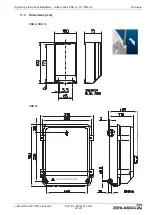
Page 25: ...del series PKE 6 10 PKE 14 Enclosure L BAL E042 GB 1002 Index 002 Part No 00163314 GB 24 26 11 3 Dimensions mm PKE 6 PKE 10 PKE 14 Switch off the main supply before removing the cover Vor ffnen des De...

Page 26: ...tance 21 L line fuse 21 M mains is connected 8 mains voltage 8 maximum control current 9 MBG 30I 18 Minimum space requirement 7 Minimum speed cut off 14 Mode 12 motor feed cable 8 motor noise 9 motor...

Page 27: ...e information If you have any technical questions while commissioning or regarding malfunctions please contact our V STE support department for control systems ventilation technology Our worldwide con...

Reviews: