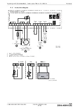
11.2.1
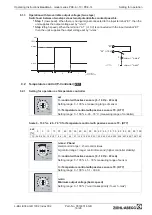
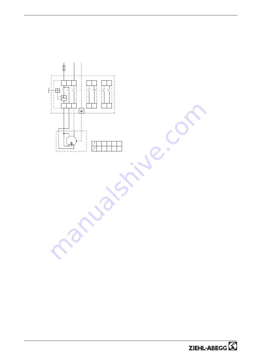
Connection diagram motor protection unit for motors with thermostats type S-ET10
•
Full motor protection by switch-off when activating the attached thermostat switches. Reset after
malfunction by key press.
•
No cut-off if the mains supply is interrupted
KT00008G
21.08.2006
PE
L
N
Netz oder geregelte Spannung
line or controlled voltage
Reseau ou tension variable
Nat eller reglerad spanning
1~ 60V...250V 50/60Hz
1
2
4
6
12
11
24
23
*
= Option
ZB / ZK(2S)
Kontaktbelastung der Hilfskontakte
contact rating of auxiliary contacts
pouvoir de coupure des contacts auxiliaires
Kontaktbelastning Larmkontakter
I >
5
max.
25A
24
110 230 400 690
U
V
6
4
4
2
1
I
A
AC15 max.
M
1~
PE
TB
U1
TB
U2
S-ET10E
ZB *
14
13
24
23
ZK(2S) *
1~ Motor
mit eingebauten Thermostatschaltern
with internal thermostats
avec thermostats intégrés
med utdragen termokontakt
Operating Instructions
Acontrol
–
model series PKE-6 /-10 / PKE-14
Enclosure
L-BAL-E042-GB 1002 Index002
Part.-No. 00163314-GB
23/26


