background image

Information

In the case of a malfunction or a failure of the equipment check all functions with alarms 
in order to prevent injury to persons or property. Note possibility of back-up operation. If 
used in intensive animal environments, any malfunctions in the air supply must be 
detected as soon as possible to prevent the development of a life-threatening situation 
for the animals. The design and installation of the system must comply with local 
regulations and directives. In Germany these include DIN VDE 0100, the animal 
protection and the keeping of working animals ordinance and the pig-keeping ordinance 
etc. Also note the instructions of AEL, DLG, VdS. 

2.4 Requirements placed on the personnel / due diligence

Persons entrusted with the planning, installation, commissioning and maintenance and 
servicing in connection with the frequency inverter must have the corresponding qual-
i

cations and skills for these jobs.

In addition, they must be knowledgeable about the safety regulations, EU/EC directives, 
rules for the prevention of accidents and the corresponding national as well as regional 
and in-house regulations. Personnel to be trained or instructed and apprentices are only 
permitted to work on the device under the supervision of an experienced person. This 
also applies to personnel undergoing general training. Comply with the legal minimum 
age. 

2.5 Start-up and during operation

Attention!

During commissioning, unexpected and hazardous conditions can arise in the entire 
installation due to defective adjustments, defective components or incorrect electrical 
connections.  Remove all persons and objects from the hazardous area.

During operation, the device must be closed or installed in a control cabinet. Fuses 
may only be replaced by new ones and must not be repaired or bypassed. The data 
for the maximum line fuse are to be considered absolutely (see Technical data). Use 
only fuses speci

ed in schematic diagrams.

Any faults detected in the electric system/modules/operating equipment must be 
corrected immediately. If these faults are not corrected, the device/system  is 
potentially very dangerous. The device/system must therefore not be operated when it 
is faulty.

Pay attention to smooth, low vibration running of the motor/fan, the appropriate 
instructions in the drive documentation must be observed!

Operating Instructions 

Acontrol

 PSET6 / PSET10

Safety instructions

L-BAL-E141-GB 1925 Index 004

Part.-No. 

6/24

Summary of Contents for Acontrol PSET6

Page 1: ...Acontrol PSET6 PSET10 Speed controller for variable voltage 1 fans Operating Instructions Keep for reference L BAL E141 GB 1925 Index 004 Part No english...

Page 2: ...2 9 Employment of external personnel 8 3 Product overview 8 3 1 Operational area 8 3 2 Maintenance 8 3 3 Transport 8 3 4 Storage 8 3 5 Disposal recycling 8 4 Mounting 9 4 1 General notes 9 4 2 Minimu...

Page 3: ...ions 16 6 3 Diagram setting signal and speed 16 6 4 Minimum speed cut off DIP 5 17 6 5 Hardstart function DIP 6 17 6 6 Operation with two variable output voltages two steps 17 7 Start up 18 7 1 Prereq...

Page 4: ...ating instructions at any time Keep the operating instructions for continued use They must be passed on to all successive owners users and nal customers 1 2 Target group The operating instructions add...

Page 5: ...arising from non intended use 2 2 Explanations of symbols Safety instructions are highlighted with warning triangles and are depicted according to the degree of hazard as follows Attention General haz...

Page 6: ...ulations Personnel to be trained or instructed and apprentices are only permitted to work on the device under the supervision of an experienced person This also applies to personnel undergoing general...

Page 7: ...e made on the device All planned modi cations must be authorized by the manufacturer in writing Use only genuine spare parts genuine wearing parts genuine accessories from ZIEHL ABEGG These parts were...

Page 8: ...The controller described is used for continuous speed adjustment on variable voltage 1 motors used to drive ventilators or pumps 3 2 Maintenance The device must be checked for soiling and if necessary...

Page 9: ...talled in a location where it will not be disturbed but at the same time can be easily accessed Depending on the housing model use supplied stoppers for cable inlets cut off necessary cable inlets res...

Page 10: ...f an electrician in accordance with electrical engineering regulations The 5 electrical safety rules must be observed It is forbidden to carry out work on electrically live parts Cover neighbouring el...

Page 11: ...onnect the shielding to one side only i e only to the control unit with the protective ground keep cable short and with as little inductance as possible 5 2 3 Harmonics current for devices 16 A Accord...

Page 12: ...r noise this noise may be dominant in the lower speed range due to the occurrence of resonance For systems where noise is critical we recommend using our Fcontrol series frequency converters with inte...

Page 13: ...ter factory setting DIP 8 ON 0 10 V modulation 0 100 Proportional the internal control of modulation with consideration n min and n max setting For enable OFF it goes not back to 0 V For motor fault t...

Page 14: ...ed Diagnostics faults Fault indicated for line fault blown internal semiconductor fuse broken controller internal voltage supply overheating by the motor thermostats TB connected When switching off vi...

Page 15: ...touch hazardous voltages directly 09 06 2011 v_pset_intern_bed VSD n max 0 100 n min 0 100 R15 ON OFF 10 9 8 7 6 5 4 3 2 1 DIP S1 R16 Potentiometer n min Minimal output voltage basic speed Setting ra...

Page 16: ...Analog Out 1 Constant voltage 10 V for exter nal potentiometer 0 10 V modulation 0 100 9 no function 10 no function 6 3 Diagram setting signal and speed Setting via external signal or external potenti...

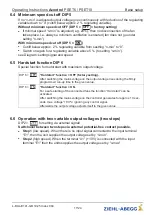
Page 17: ...ng the mains voltage on the output voltage rises during the rmly programmed run up time to the given value DIP 6 ON Hardstart function ON For a safe starting of the connected fans the function Hard st...

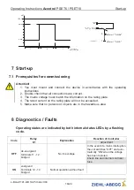
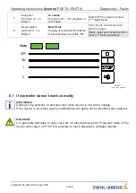
Page 18: ...late will not be exceeded 5 Make sure that no persons or objects are in the hazardous area 8 Diagnostics Faults Operating states are indicated by both internal status LEDs by a ashing code Code Relay...

Page 19: ...de 09 06 2011 v_flash_code_pset VSD 2 1 ON OFF 8 1 If controller doesn t work correctly Information Setting of dip switches in principle only when device is not under voltage If the device is on mains...

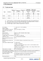
Page 20: ...or current approx 0 2 A Voltage supply e g for sensors 24 V 20 Imax 250 mA Output 0 10 V Imax 10 mA short circuit proof Max permissible ambient tem perature 55 C Min permissible ambient tem perature 0...

Page 21: ...ature above the rated temperature see following table The average value measured during a 24 h period must be 5 K under the max ambient temperature For installation in a switch cabinet the device s di...

Page 22: ...ltern with internal thermostats 2 A1 GND Ausgang Output 0 10 V Imax 10 mA 3 E1 GND GND Eingang Input 0 10 V 4 PEUN17K4 08 06 2011 TB TB D1 D1 24V Kontaktbelastung Contact rating max AC 250 V 5 A 5 1 L...

Page 23: ...9 3 Dimensions mm PSET6 PSET10 Operating Instructions Acontrol PSET6 PSET10 Enclosure L BAL E141 GB 1925 Index 004 Part No 23 24...

Page 24: ...4 info ziehl abegg de http www ziehl abegg de 9 5 Service information If you have any technical questions while commissioning or regarding malfunctions please contact our technical support for control...

Reviews: