5 Electrical installation
5.1 Safety precautions
Danger due to electric current
•
Work on electric components may only be carried out by trained electricians
or by persons instructed in electricity under the supervision of an electrician
in accordance with electrical engineering regulations.
•
It is forbidden to carry out work on electrically live parts.
5.2 Voltage supply
The voltage supply to the add-on module is provided automatically by the connector to
the base board.
No other voltage sources are necessary.
5.3 Communication
5.3.1 Connecting at the AM-LON Modul
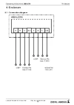
The two-wire lead of the LON
®
-bus is connected to terminals
“
NET_A
”
and
“
NET_B
”
.
The correct choice of cable is essential for the proper operation of the network.
Recommended wire types
•
22AWG, twisted pair, typical solid an unshilded
•
Remote control line JY (St) Y 2x2x0.6
•
Wieland line system (gesis con)
The connection of the LON
®
bus is not polarity sensitive. When using cable with more
than two strands, ensure that two twisted strands only are used for the network line. The
parallel laying
of several strands is
not
permitted!
Information
The maximum line length for free wiring is 500 m and the maximum distance between
two devices is 400 m.
The maximum line length for wiring in bus topology is 1000 m.
(
Wiring and terminating resistor in the LON
®
network)
Operating Instructions
AM-LON
Electrical installation
L-BAL-E166-GB 1610 Index 002
Part.-No. 00163375-GB
6/9


