background image

AMblue

Fan with asynchronous motor and mounted frequency inverter

Assembly instructions

Keep for reference!

L-BAL-F069-GB 1735 Index 004

Part.-No. 00703523-GB

english

Summary of Contents for AMblue

Page 1: ...AMblue Fan with asynchronous motor and mounted frequency inverter Assembly instructions Keep for reference L BAL F069 GB 1735 Index 004 Part No 00703523 GB english ...

Page 2: ... Design ER 9 4 4 Optimal installation distances according to for RH ER GR fans 11 4 5 Assembly in a humid atmosphere 11 4 6 Connection lead terminal box 11 4 7 Cable inlet 11 5 Electrical installation 12 5 1 Safety precautions 12 5 2 Terminal compartment 13 5 3 EMC compatible installation of control lines 13 5 3 1 Control cables 13 5 3 2 Harmonics current for devices 16 A 13 5 3 3 Harmonics curren...

Page 3: ...up 21 7 1 Prerequisites for commissioning 21 8 Diagnostics Faults 22 8 1 Trouble shooting 22 8 2 Status Out with flash code 23 9 Service work 25 9 1 Repairs maintenance 25 9 2 Cleaning 26 10 Enclosure 27 10 1 Technical data 27 10 2 Connection diagram 29 10 3 EC Declaration of Incorporation 30 10 4 Index 31 10 5 Manufacturer reference 32 10 6 Service information 32 Assembly instructions AMblue L BAL...

Page 4: ...modifications 1 4 Copyright These assembly instructions contain copyright protected information The assembly instructions may be neither completely nor partially photocopied reproduced translated or put on data medium without previous explicit consent from ZIEHL ABEGG SE Infringements are liable for damages All rights reserved including those that arise through patent issue or registration on a uti...

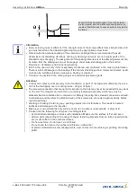
Page 5: ...n a flawless condition and installed and operated in compliance with the assembly instructions and or operating instructions Operating out side the device s technical specifications see name plate and attachment technical data can lead to a defect in the device and additional damage Information A separate fault and performance monitoring system with an alarm signal function is necessary in order to ...

Page 6: ... not wear loose or hanging clothing jewellery etc tie together long hair and cover it Attention High temperatures can occur on the motor surfaces and on the controller housing Even after switching off dangerous temperatures can still occur in and on the device 2 7 Modifications interventions in the device Attention For reasons of safety no unauthorized interventions or modifications may be made on t...

Page 7: ...drant drives This assembly manual describes combinations of fans and frequency inverters in different models and frame sizes 3 3 Criteria for long service life The service life of devices with power electronics is decisively dependent on the ambient temper atures The longer electronic components are exposed to high ambient temperatures the faster the deterioration and the more probable the failure...

Page 8: ...on Recommendation Turn the impeller evenly by hand to avoid jamming and damaging the bearing Do not lift the fan by the frequency inverter 3 6 Disposal recycling Disposal must be carried out professionally and in an environmentally friendly way in accordance with the respective national legal stipulations Separate the materials by type and in an environmentally friendly way If necessary commission...

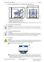
Page 9: ...endent on not being subjected to unusual sudden or mechanical loads or stresses on the material min ambient temperature Technical data Corrosion is possible at the cutting edges on sendzimir galvanised parts Before the first switch on remove any items that may be present borings screws and other foreign objects from the intake area risk of injury from any objects that may fly out 4 2 Permissible pos...

Page 10: ...t points securely to the foundation or plant If not fastened sufficiently there is a risk of the fan tipping over or coming loose danger of injury The screwed connection that connects the impeller to the hub may never be loosened for any work on the fan The impeller and hub form a commonly balanced assembly which may only be disassembled and installed as a complete unit Merely loosening this screwe...

Page 11: ...pe elbows If a terminal box is mounted near to the fan this must be installed lower than the mounted PMIcontrol to ensure that water cannot penetrate through the connecting cables 4 7 Cable inlet Attention Only use lines which can guarantee a permanent seal around the cable glands pressure resistant dimensionally stable round centred jacket e g by means of gusset filling Lines with filling fleece are...

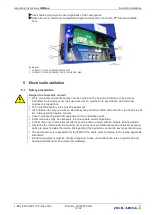
Page 12: ...en after disconnection the dc link is still live Always wait at least 3 minutes Cover neighbouring electrical equipment during installation work Other measures may be necessary to achieve safe electrical isolation Connect fan only to electrical circuits that can be disconnected with an all pole isolating switch Operating the device with the housing cover removed is prohibited because energized exp...

Page 13: ...Connection diagram 5 3 EMC compatible installation of control lines 5 3 1 Control cables Pay attention to sufficient distance from powerlines and motor wires to prevent interferences The control cable may not be longer than 30 m Screened control cables must be used when the cable length is longer than 20 m When using a shielded cable connect the shielding to one side only i e only to the control un...

Page 14: ...ding on the used cable the type of routing the operating conditions and according to the standards applicable on site The specification for the maximum admissible line fuse of the device must be observed see technical data Possible components for the line protection recommendation Safety fuses of operating class gG whole range fuse cartridges for general applications according to EN 60269 1 Line pr...

Page 15: ...fan speed Connection E1 GND Analog In 1 The internal jumper E1 1 is factory set in the position for a 0 10 V or PWM speed setting signal For a 0 20 mA signal the plug E1 1 must be replugged Danger due to electric current Do not replug the jumper under voltage observe the safety instructions Make sure the signal has the correct polarity Never apply line voltage to analog inputs Possibilities for sp...

Page 16: ...4 V DC Out 24 V 15 28 V GND E1 E1 1 PWM 10 V E1 D1 GND 10V Analog In 1 10 V DC Out 24V 24 V DC Out PWM f 1 10 kHz 10 kΩ 0 20 mA Control via external setting signal 0 20 mA E1 D1 GND 0 20 mA Analog In 1 E1 1 mA 13 06 2014 i_jumper_motor_mounted_0_20ma eps Assembly instructions AMblue Electrical installation L BAL F069 GB 1735 Index 004 Part No 00703523 GB 16 32 ...

Page 17: ...h other It is not permissible to connect voltage outputs in the device to each other 5 9 Voltage supply for external devices 24V GND A voltage supply is integrated for external devices e g a sensor max current load see technical data In case of overload or short circuit 24 V GND the external power supply is shut down multi fuse The device performs a Reset and continues operation It is not permissi...

Page 18: ... LED can be controlled by using a pull up resistor This lights when the output Status Out OC OC Open Collector is on GND potential The details of which pull up resistor needs to be used depend on the specification on the LED that is used Pull Up 10V OC GND 10 12 2015 i_pmi_basic_status_oc eps 200 300 Ω Display by LED in 5 step potentiometer type ZSG 5 In the case of the speed setting via the 5 step...

Page 19: ...M MODBUS W 349050 AM CAN OPEN 349064 CANOPEN module To integrate the device into a CANOPEN network AM LON 349049 LON module To integrate the device into a LON network AM PROFIBUS 349063 PROFIBUS module To integrate the device into a PROFIBUS network AM ETHERCAT 349071 ETHERCAT module To integrate the device into an ETHERCAT network For basic operation with limited MODBUS access 6 Parameter memory ...

Page 20: ... leave it plugged into the device to avoid losing it Attention It is not allowed to use a ZAstick that is intended for another fan The fan could be parametrised with a speed which exceeds the maximum permissible speed of the fan impeller This can damage or destroy the impeller Status LED frequency inverter Number of flashes Description 2 One or more data records were loaded successfully 3 No ZAstic...

Page 21: ...the fan area 3 That safety devices if necessary are mounted EN ISO 13857 4 The impeller is out of reach 5 Are the condensation water drains holes as far as available open or respectively closed according to the suitable installation position 6 Connection data complies with the specifications on the rating plate During start up check the following 1 Check the direction of rotation rotation direction...

Page 22: ...scrapes brushes When indicated clear foreign bodies dirt from the fan Active temperature management effective Motor or electronics overheated Check for free air passages remove foreign bodies if necessary see Impeller blocked or dirty Check temperature of supply air Check installation space air speed over heat sink Air flow to low Fan turns too slowly see Fan turns too slowly Airways blocked Check ...

Page 23: ...to too high inside temperatures In case of a temperature rise above the fixed limits the modulation is reduced linearly To prevent the complete system being switched off externally in this op eration permissible for the controller in case of reduced operation due to too high an internal temperature no fault message is sent via the relay With a drop in temperature the modula tion rises again llinear...

Page 24: ... following a defined number of permitted starting tests Permitted starting tests dependant on fault message IGBT and shortcut earth 3 x IGBT Ready 5 x Load driver 8 x Cooling off interval dependant on fault message IGBT and shortcut earth 70 s IGBT Ready 10 s Load driver 2 s Reset by enable or line voltage ON OFF 7 de energized 13 14 interrupted Intermediate undervoltage Intermediate circuit voltag...

Page 25: ...nd does not switch on again Check motor and connection then reset Motor protection 17 de energized 13 14 interrupted Temperature err Excess of the max permissible compo nent temperature Controller switches off motor Automatic restarting after cooling down Check cooling of the controller 18 de energized 13 14 interrupted System internal error Motorcontrol error group System Possible causes Current ...

Page 26: ...cular operating conditions such as vibrations humidity or soiling in the bearing unfavourable control modes etc are present Please consult our Service Department with regard to changing the bearing as for all other damage e g to the coil or electronics Regular inspection and possibly cleaning is necessary to prevent imbalance and blockage of the condensation bores due to ingress of dirt When openi...

Page 27: ...nsation does not occur Permissible installation height 0 4000 m amsl 1000 m no limitation 1000 m max permissible input current current indication rating plate minus 5 1000 m 2000 m max permissible line voltage max voltage indication rating plate minus 1 29 100 m Permissible rel humidity Motor The motor is released for a relative humidity of 100 at continental climate without other ambient influence...

Page 28: ... connection these devices are to be classified as category C2 devices according to the relevant EN 61800 3 The increased requirements placed on electrical interference 2 kHz for category C1 devices are complied with in addition Max line fuse on site line protection fuse according to EN 60204 1 Classification VDE0113 Part 1 see also Assembly instructions Electrical installation Mains connection Line ...

Page 29: ...d M 3 q 6 PMIcontrol Basic M FSDM UMUN18K2 15 12 2016 2 Nicht für IT System geeignet Not suitable for IT system TB TP TB TP W V U 3 Motor mit eingebauten Temperaturfühlern with internal thermistors 7 U V W PE TP TP 1 Line 3 380 V 480 V 50 60 Hz 2 Not suitable for IT system 3 Contact rating max 2A 250 V AC 4 Interface for transferring the motor fan parameters with ZAstick 5 Input 0 10 V 0 20 mA 0 1...

Page 30: ...sment and risk reduction EN ISO 13857 2008 Safety of machinery safety distances to prevent danger zones being reached by the upper limbs Note The maintenance of the EN ISO 13857 2008 relates only to the installed accidental contact protection provided that it is part of the scope of delivery The specific technical documentation in accordance with Appendix VII B has been written and is available in ...

Page 31: ... 7 F flashing code 23 frequency inverter 7 G grease service life 26 I Imbalance 22 Input resistance 27 L leakage current 14 27 line fuse 28 line impedance 13 line protection 14 M mains 14 mains interruption 24 Max Speed 17 Min Speed 17 modulation 23 motor protection 13 15 motor speed 17 O one quadrant drives 7 overload 24 25 P parameter memory 19 PTC 15 PWM 16 R rating plate 21 26 relays 18 Reset 2...

Page 32: ...ontact our technical support for control systems ventilation technology phone 49 0 7940 16 800 Email fan controls service ziehl abegg de Our worldwide contacts are available in our subsidiaries for deliveries outside of Germany see www ziehl abegg com If you make returns for inspections or repairs we need certain information in order to facilitate focused trouble shooting and fast repair Please us...

Reviews: