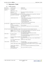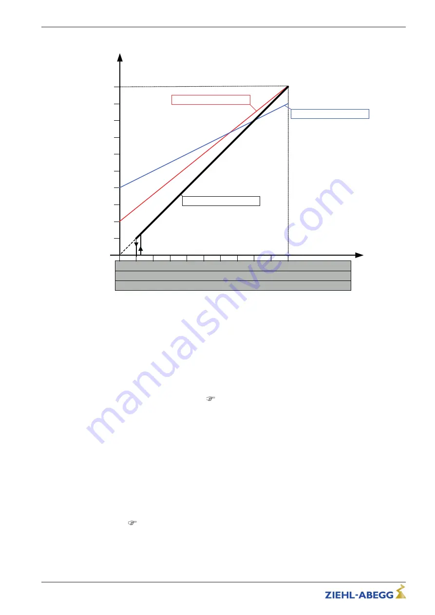
Diagram setting signal and motor speed
nM
26.08.2015
v_amblue_set_min_max.vsd
1
2
3
4
5
6
7
8
9
10
Analog In 1
80
70
60
50
40
30
20
10
0...10 V
10
20
30
40
50
60
70
80
90
100 0...100 % PWM
0
0
90
100 %
n-min 0 % n-max. = 100 %
n-min 40 % n-max. = 90 %
n-min 20 % n-max. = 100 %
2
4
6
8
10
12
14
16
18
20
0
0...20 mA
Example (characteristic depending on respective motor design)
nM
Motor speed
100 % Rated speed
Analog In 1
Speed setting signal (0 - 10 V, 0...20 mA, 0...100 % PWM)
n-min
Min. Speed in Hz, adjustable via communication module
n-max
Max. Speed in Hz, adjustable via communication module
5.8
Output voltage
“
10 V
”
Voltage supply e.g. for speed setting by external potentiometer.
Connection:
“
10 V
”
-
“
GND
”
(max. load
Technical data und connection diagram).
•
It is not permissible to connect voltage outputs of several devices to each other!
•
It is not permissible to connect voltage outputs in the device to each other!
5.9
Voltage supply for external devices (+24V, GND)
A voltage supply is integrated for external devices e.g. a sensor (max. current load see technical
data).
In case of overload or short circuit (24 V
–
GND), the external power supply is shut down (multi-fuse).
The device performs a
“
Reset
”
and continues operation.
•
It is not permissible to connect voltage outputs of several devices to each other!
•
It is not permissible to connect voltage outputs in the device to each other!
5.10
Digital input
“
D1
”
for enable (device ON / OFF)
Electronic ON / OFF control via
fl
oating contact at terminals
“
D1
”
-
“
+24V
”
(input resistance and
voltage range
Technical data).
Function factory setting for
“
D1
”
:
•
Device
“
ON
”
for closed contact.
•
Device
“
OFF
”
with opened contact.
Activation via
fl
oating contacts, a low voltage of approx. 24 V DC is connected.
Assembly instructions
AMblue
Electrical installation
L-BAL-F069-GB 1735 Index 004
Part.-No. 00703523-GB
17/32


