background image

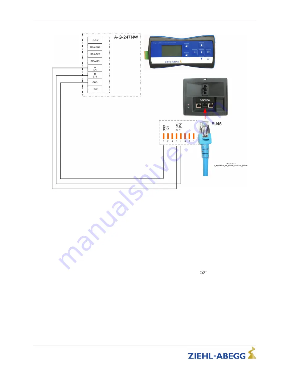
Connection with RJ45 patch cable whe using the connection box for ECblue 

The connection is made at the terminals: A (D+), B (D-) und GND.
The connection is made to the connection box by the RJ45 service connection.

5.9 Communication

5.9.1 RS-485 interface for MODBUS

The device comes equipped with a RS-485 interface for networking via MODBUS. 
Conntection at: 

A (D+)

B (D-)

 and 

GND

Addressing is performed by an external terminal or a PC with the appropriate software.
Automatic addressing can be started when the connections 

ID1

 and 

ID2

 for 

Address-

ing

 are connected with each other additionally next to the bus connection. I. e. it is no 

longer necessary to address every user manually in the network (

  MODBUS network-

ing and automatic addressing). 

For automatic addressing with hand held terminal type A-G-247 and digital control and 
display unit NETcon type A-G-102ANE max. 

63

 members, with control module UNIcon 

MODBUS Master max. 

32

 members. 

Assembly instructions 

ECblue MODBUS

Electrical installation

L-BAL-F041-GB 1820 Index 003

Part.-No. 00296941-GB

18/36

Summary of Contents for ECBLUE MODBUS

Page 1: ...ECblue MODBUS Application Cleanroom EC fans and motors with highest ef ciency Assembly instructions Software version D2324A from version 10 04 L BAL F041 GB 1820 Index 003 Part No 00296941 GB english ...

Page 2: ...nt of external personnel 7 3 Product overview 8 3 1 Application operational area 8 3 2 Functional description 8 3 3 Criteria for long service life 8 3 4 Note on the ErP directive 8 3 5 Transport storage 9 3 6 Disposal recycling 10 4 Mounting 10 4 1 General notes 10 4 2 Connection lead terminal box 11 4 3 Mounting of centrifugal fans 11 4 3 1 Mounting of centrifugal fans RH design 11 4 4 Mounting t...

Page 3: ... status tacho 21 5 11 Open Collector output A2 operation 21 5 12 Potential at control voltage connections 21 6 Start up 22 6 1 Prerequisites for commissioning 22 7 Diagnostics Faults 23 7 1 Trouble shooting 23 7 2 Indication of the operating condition over A1 and A2 24 7 3 Behaviour in rotation by air current in reverse direction 27 8 Service work 27 8 1 Repairs maintenance 27 8 2 Cleaning 29 9 En...

Page 4: ...ions and the described hardware and software in the device has been examined It is still possible that non compliances exist no guarantee is assumed for complete conformity To allow for future developments construction methods and technical data given are subject to alteration We do not accept any liability for possible errors or omissions in the information con tained in data illustrations or dra...

Page 5: ...d explosive gaseous media Use in areas at risk of explosion for conveying gas mist vapours or mixtures of the above Transfer of solids or solids content in the transfer medium Operation with iced up fan impellers Conveyance of abrasive or adhesive media Conveyance of liquid media Use of the fan and add on parts e g safety grille as a resting surface or climbing aid Fans are not designed for walkin...

Page 6: ...age Information A separate fault and performance monitoring system with an alarm signal function is necessary in order to prevent personal injuries and material damages during malfunc tions and in case the device fails Substitute operation must be taken into consideration The design and installation of the system must comply with local regulations and directives 2 5 Requirements placed on the pers...

Page 7: ...ral notes When the motor runs independently due to air flowing through or if it continues to run down after being turned off dangerous voltages of over 50 V can arise on the motor internal connections through operation of the generator The safe isolation from the supply must be checked using a two pole voltage detector Even after disconnecting the mains voltage life threatening charges can appear b...

Page 8: ...order only The device may only be used as intended see Application You must periodically examine the safety equipment for their properly functioning condition The assembly instructions and or operating instructions are always readily available at the location where the device is being used are complete and are in legible condition These persons are regularly instructed in all applicable questions ...

Page 9: ... for fans with motor size D MK116 _ I _ _ _ _ _ Axial fans type F _ _ _ _ _ I _ D _ _ _ _ _ Centrifugal fans type RH _ _ _ _ I _ D _ _ _ GR _ _ _ _ I _ D _ _ _ ER _ _ _ _ I _ D _ _ _ 3 3 Criteria for long service life The service life of devices with power electronics is decisively dependent on the ambient temperatures The longer electronic components are exposed to high ambient temper atures the ...

Page 10: ...ve transport equipment could cause death Store the fan motor in the original packaging in a dry area protected from the weather and protect it from dirt and weather until final installation Avoid prolonged storage we recommend a maximum of one year consult the manufacturer before starting if stored for longer Inspect the bearing for proper operation prior to installation Recommendation Turn the imp...

Page 11: ...fting beam Attachment points are solely the holes on the housing flange motor bed support plate motor suspensions fastening brackets and any crane eyes of the fan depending on the shape of the fan The chain rope may not touch the impeller and the possibly mounted frequency inverter when lifting with the lifting beam otherwise damage is possible At a weight greater than 25 kg for men 10 kg for women...

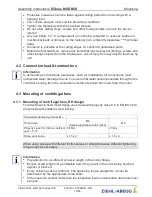
Page 12: ... through to the controller housing from the connections install a terminal box lower than the motor 4 3 Mounting of centrifugal fans 4 3 1 Mounting of centrifugal fans RH design For attachment to fixed motor flange use screws with property class 8 8 to EN ISO 4014 and provide with suitable screw locking Permissible tightening torques MA Thread size M6 Special application with 5 pitch M8 Property cla...

Page 13: ...drive for fans During assembly of the fan impellers or other components no inadmissible force may be applied to the motor bearing Centre the fan impeller accurately and mount without tension on the rotor flange the fan wheel must lie flat Use suitable screws for fastening the fan impeller on the rotor flange and fit as suitable screw lock Every screwing case must be tested for suitability The permissi...

Page 14: ...ctricity under the supervision of an electrician in accordance with electrical engineering regulations The 5 electrical safety rules must be observed It is forbidden to carry out work on electrically live parts Even after disconnection the dc link is still live Always wait at least 3 minutes Cover neighbouring electrical equipment during installation work Other measures may be necessary to achieve...

Page 15: ..._reinr vsd 1 2 PE N L1 GND A1 A2 10 V A B ID1 ID2 3 1 Connection control Molex micro fit 3 0 8 pole 43045 43045 2 Connection line AMP 3 pole MATE N LOK 350789 3 3 Do not loosen the screws from the housing Information Connection to the terminals is only permissible with compatible counterparts not included in delivery Assembly instructions ECblue MODBUS Electrical installation L BAL F041 GB 1820 Ind...

Page 16: ...icated line voltage of the device To activate the on current limitation you must wait at least 90 seconds after switching off the line voltage before switching back on 5 4 2 Required quality attributes for the mains voltage Danger due to electric current The mains voltage must comply with the EN 50160 quality characteristics and the defined standard voltages in IEC 60038 5 5 Residual current operat...

Page 17: ... service If necessary an external terminal can be connected This can be e g necessary to adapt the pre setting during start up For information about the current operating condition a terminal can be permanent attached The voltage supply of the terminal is made by the accumulators inserted there or the plug power supply unit Connection by terminals with telephone wire 04 03 2013 v_a g 247nw_an_ecbl...

Page 18: ...a PC with the appropriate software Automatic addressing can be started when the connections ID1 and ID2 for Address ing are connected with each other additionally next to the bus connection I e it is no longer necessary to address every user manually in the network MODBUS network ing and automatic addressing For automatic addressing with hand held terminal type A G 247 and digital control and disp...

Page 19: ...CAT5 cable is internally connected to PE by an RC element Another 63 users are connected by a repeater in manual addressing no connection of connections ID1 ID2 If a repeater is necessary and automatic addressing should be carried out only the repeater of the Z G 1NE type can be used only it can relay the addressing signal The connections for the automatic addressing ID1 and ID2 are not directly c...

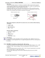
Page 20: ... GND white Default interface parameter Baudrate 19200 Bits 8 Parity Even Stop bits 1 Handshake none Information The MODBUS register description and the information sheet Network structure of MODBUS can be requested from our Support Department V STE for control systems ventilation 5 9 2 MODBUS networking and automatic addressing On the first user that is connected directly to a terminal MODBUS Maste...

Page 21: ... D B D GND and ID1 ID2 Networking with RJ45 patch cable by usage connection box for ECblue The connection to the terminal is made at the terminals A D B 1D and GND Connection of the members via the two RJ45 connections BUS1 and BUS2 Assembly instructions ECblue MODBUS Electrical installation L BAL F041 GB 1820 Index 003 Part No 00296941 GB 21 36 ...

Page 22: ...eps 200 300 Ω A1 more specifications Technical data 5 11 Open Collector output A2 operation Via the output A2 Operation Out OC an operating indication is possible With the output voltage 10 V a standard LED low power LED can be controlled by using a pull up resistor This lights when the output A2 Operation Out OC OC Open Collec tor is on GND potential By fault the output A2 is switched to GND poten...

Page 23: ...plies with the specifications on the rating plate During start up check the following 1 Check the direction of rotation rotation direction arrow on the fan blade impeller base plate or support plates on suction side or rating plate 2 Check for quiet low vibration operation Strong vibrations due to erratic operation unbalanced e g caused by transportation damage or improper use can lead to failure 3...

Page 24: ...rong direction Motor turns in wrong direc tion at high speed Check air stream see behaviour in rotation by air current in reverse direc tion see Fan does not run Fan turns too slowly Impeller blade scrapes brushes When indicated clear foreign bodies dirt from the fan Active temperature manage ment effective Motor or electronics over heated Check for free air passages remove foreign bodies if nec e...

Page 25: ...LED Installation Output A1 Status Out OC ON A1 Status Out OC GND potential A1 Status Out OC with flash code 11 02 2009 v_flash_explain VSD 3 x 2 x ON OFF 4 x 5 x 6 x 1 x 7 x 8 x 9 x Via the output A2 Operation Out OC an operating indication is possible activation of a LED Installation Output A2 Operation Out OC ON A2 Status Out OC GND potential A2 Operation Out OC 14 02 2011 v_on_off_explain VSD ON...

Page 26: ...gnised Replace fan motor 5 x ON Motor blocked If after 8 seconds of commutation no speed is measured 0 the fault Motor blocked is released EC Controller switches off re newed attempt to start after about 2 5 sec Final shutoff when fourth starting test fails It is then necessary to have a reset by disconnecting the line voltage Check if motor is freely rotatable 6 x ON IGBT Fault Short circuit to e...

Page 27: ... the target direction of rotation after the error message the error message will disappear Should a voltage interruption occur in the meantime the time taken up to the switch off will begin again Check if motor is freely rotatable Check if the fan is driven in re verse direction by an air stream Behaviour in rotation by air current in reverse direction 12 x ON Line voltage too low If the DC link v...

Page 28: ...of the device and cooling of the controller for factory programmed function Fault indication inverted 7 3 Behaviour in rotation by air current in reverse direction In the STOP state no release no preset signal no voltage supply the motor controller does not intervene when the fan turns in the wrong direction e g due to a draught If the fan is started voltage ON while being driven in the opposite d...

Page 29: ...he product is not suited are conveyed the severe corrosion may result in the impeller breaking Any impellers corroded in this way must be replaced immediately Deposits on the motor particularly on the cooling vanes and in recesses on the rotor can lead to reduced cooling performance and the motor switching off prematurely For this reason remove deposits quickly see chapter Cleaning Maintenance int...

Page 30: ... interrupted and secured against restoration Clean the fans s flow area Attention Do not use any aggressive paint solvent cleaning agents when cleaning Make sure that no water gets inside the motor and the electronics e g by direct contact with seals or motor openings observe protection class IP The condensation bores if available corresponding to the installation position must be checked for free ...

Page 31: ...oltage indication rating plate minus 1 29 100 m Permissible rel humidity 85 no condensation Permissible temperature range for storage and transport 30 80 C Electromagnetic compatibility for the standard voltage 230 400 V according to DIN IEC 60038 Interference emission EN 61000 6 4 industrial applications Interference immunity EN 61000 6 2 industrial applications Harmonics current Active power fac...

Page 32: ...ND Status Out OC A1 Operation Out OC A2 A D MODBUS RS 485 1 2 3 4 5 6 7 8 8 2 Signalanschluss Signal connection 1 Line voltage 1 200 277 V 50 60 Hz 2 Signal connection Information Connection to the terminals is only permissible with compatible counterparts not included in delivery Assembly instructions ECblue MODBUS Enclosure L BAL F041 GB 1820 Index 003 Part No 00296941 GB 32 36 ...

Page 33: ...ix I Articles 1 1 2 1 1 5 1 4 1 1 5 1 in EG Machinery Directive 2006 42 EG Manufacturer ZIEHL ABEGG SE Heinz Ziehl Strasse D 74653 Künzelsau The following harmonised standards have been used EN 60204 1 2006 A1 2009 Safety of machinery electrical equipment of machines Part 1 General requirements EN ISO 12100 2010 Safety of machinery General principles for design Risk as sessment and risk reduction ...

Page 34: ... The transmission can be electronic on data carriers or on paper All industrial property rights remain with the above mentioned manufacturer It is prohibited to commission this incomplete machine until it has been secured that the machine into which it was incorporated complies with the stipulations of the EC Machinery Directive Künzelsau 12 12 2017 ZIEHL ABEGG SE Dr W Angelis Technical Director V...

Page 35: ... 14 cooling 28 D DC voltage 15 E ErP directive 9 F flash code 24 G grease service life 28 I Imbalance 23 interface parameter 19 L leakage current 30 M MODBUS 17 motor flange 12 motor speed 21 Motors Type 8 O one quadrant drives 8 R rating plate 29 Residual current operated protective 15 RJ45 17 RS 485 18 S S1 operated 8 service life 8 sound power levels 22 Status display 21 Switching Freq 29 T tempe...

Page 36: ...04 info ziehl abegg de http www ziehl abegg de 9 6 Service information If you have any technical questions while commissioning or regarding malfunctions please contact our technical support for control systems ventilation technology phone 49 0 7940 16 800 Email fan controls service ziehl abegg de Our worldwide contacts are available in our subsidiaries for deliveries outside of Ger many see www zi...

Reviews: