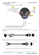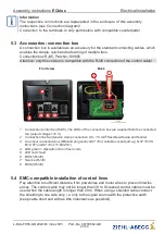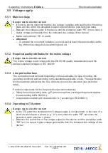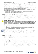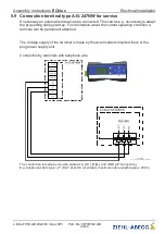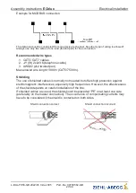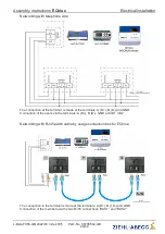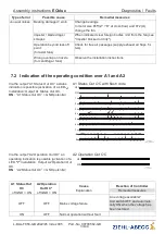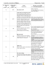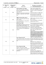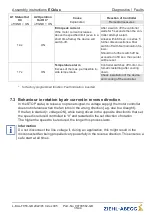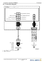
When using telephone cable with four cable cores, we recommend the following
allocation:
•
A (D+) = red
•
B (D-) = black
•
ID1 - ID2 = yellow
•
GND = white
Default interface parameter
•
Baudrate = 19200
•
Bits = 8
•
Parity = Even
•
Stop bits = 1
•
Handshake = none
Information
The MODBUS register description and the information sheet
“
Network structure of
MODBUS
”
can be requested from our Support Department V-STE for control systems -
ventilation.
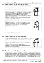
5.10.2 MODBUS networking and automatic addressing
On the
fi
rst user that is connected directly to a terminal, MODBUS Master or PC,
“
GND
”
and
“
ID1
”
or
“
ID2
”
must be bridged. This is recognised as a result and occupied by
address
1
.
For the following users the connection
“
ID1
”
or
“
ID2
”
of a user respectively is connected
with connection
“
ID1
”
or
“
ID2
”
of the next user.
The automatic addressing of other users is initiated by the previous user via this
connection.
Assembly instructions
ECblue
Electrical installation
L-BAL-F056-GB 2022/45 Index 005
Part.-No. 00700562-GB
28/44


