5.4
Communication
5.4.1
Bus connection
The connection is made using the RJ45 sockets, Bus 1 and Bus 2. A minimum of CAT5 (STP) are
recommended as the cables. The cable shield is connected to PE by an RC element inside the
connection box.
As well as a Service PIN message at the LON node being triggered by a magnet (see Connection
components chapter), it can alternatively be triggered at any time by applying a brief 5 V (+- 10%,
typical 5 mA) voltage pulse of typically 0.5 s at PIN 7 (GND) and PIN 8 (+5V).
Using the Service connection,m this can also be done with the bus wiring connected to BUS1 and
BUS2.
Information
The wiring connected to the connection box is always based on the bus topology. With the
recommended CAT5 patch cable, the maximum cable length is 500 m.
(
Wiring and terminator in the LON
®
network)
5.4.2
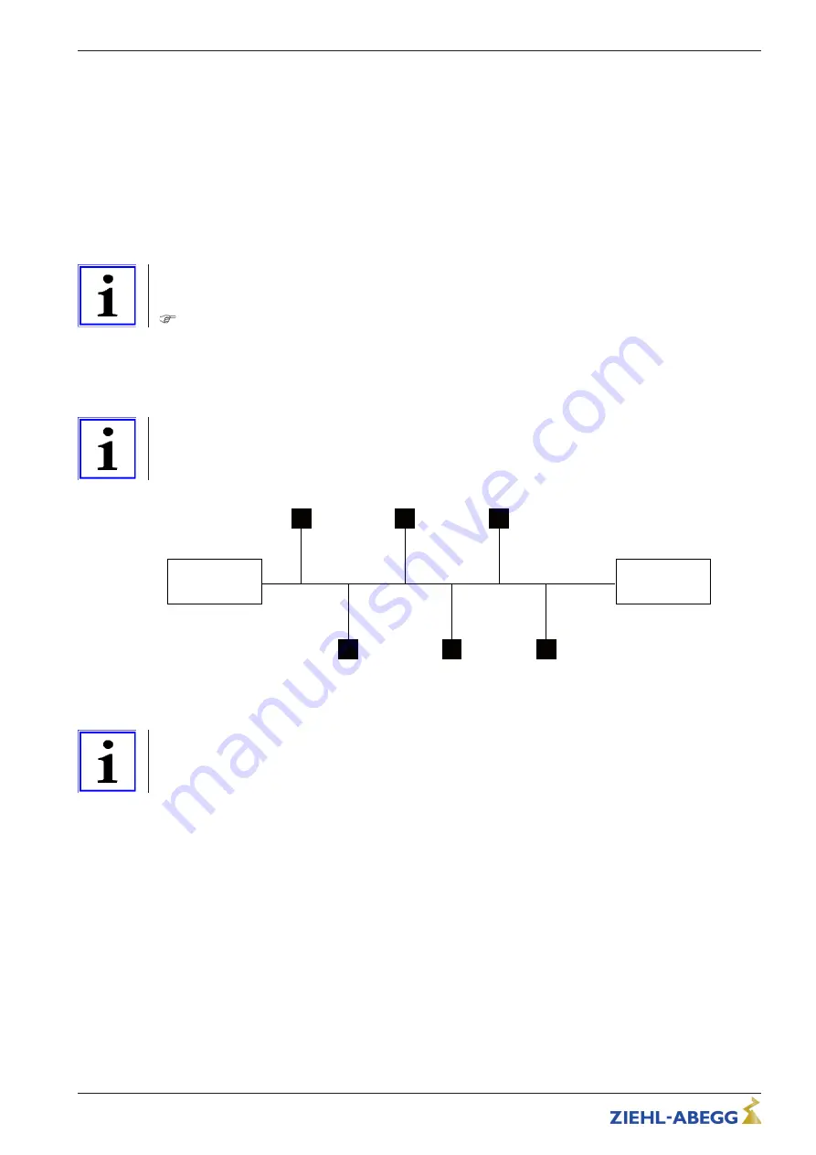
Wiring and terminating resistor in the LON
®
network
With bus wiring, a terminating resistor of 100
Ω
/
≤
0.25 W must be
fi
tted to the beinning and end of
the line.
Information
The stub lines to the individual devices should be kept as short as possible (max. 5 m).
Example: bus wiring
02.02.2012
v_busverdr_lon.VSD
100 ohm
100 ohm
100 ohm
= terminating resistor
Information
If any matters are unclear, you can send for our technical information sheet "Network structure of a
LON
®
" - TIL00_35. It contains information about the topology, circuitry and selection of types of cable.
Operating Instructions
Connection box ECblue (LON)
Electrical installation
L-BAL-E268-GB 1630 Index 003
Part.-No.
6/10


