5.12
Digital input
“
1D
”
for
“
100% function
”
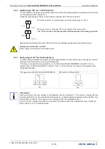
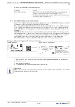
You can switch over between automatic speed control by the setting signal and operation at full speed
via the digital input D1 (Digital In 1).
Activation via
fl
oating contacts, a low voltage of approx. 24 V DC is connected.
24V
D1
Digital In 1
0 – 100 %
29.06.2012
v_D1_24V_0_100prz.vsd
With closed contact = automatic speed control by setting signal 0...100 %
24V
D1
Digital In 1
29.06.2012
v_D1_24V_100prz.vsd
100 %
With open contact = full speed (100 %) regardless of the setting signal.
The
“
100 % function
”
enables operation at full speed when the setting signal fails.
Main switch for ECblue fans with
“
100% function
”
see chapter accessories main switch Zenec.
Danger due to electric current
Never apply line voltage to the digital input!
5.13
Relay output
“
K1
”
for fault indication
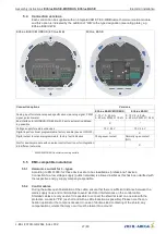
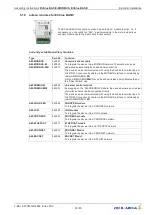
An external fault indicator is available over the potential-free contact of the built-in relay (max. contact
rating see Technical data and connection diagram).
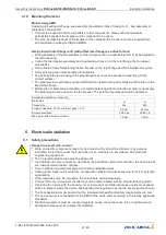
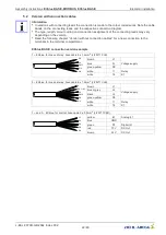
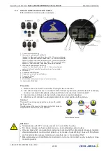
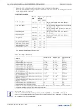
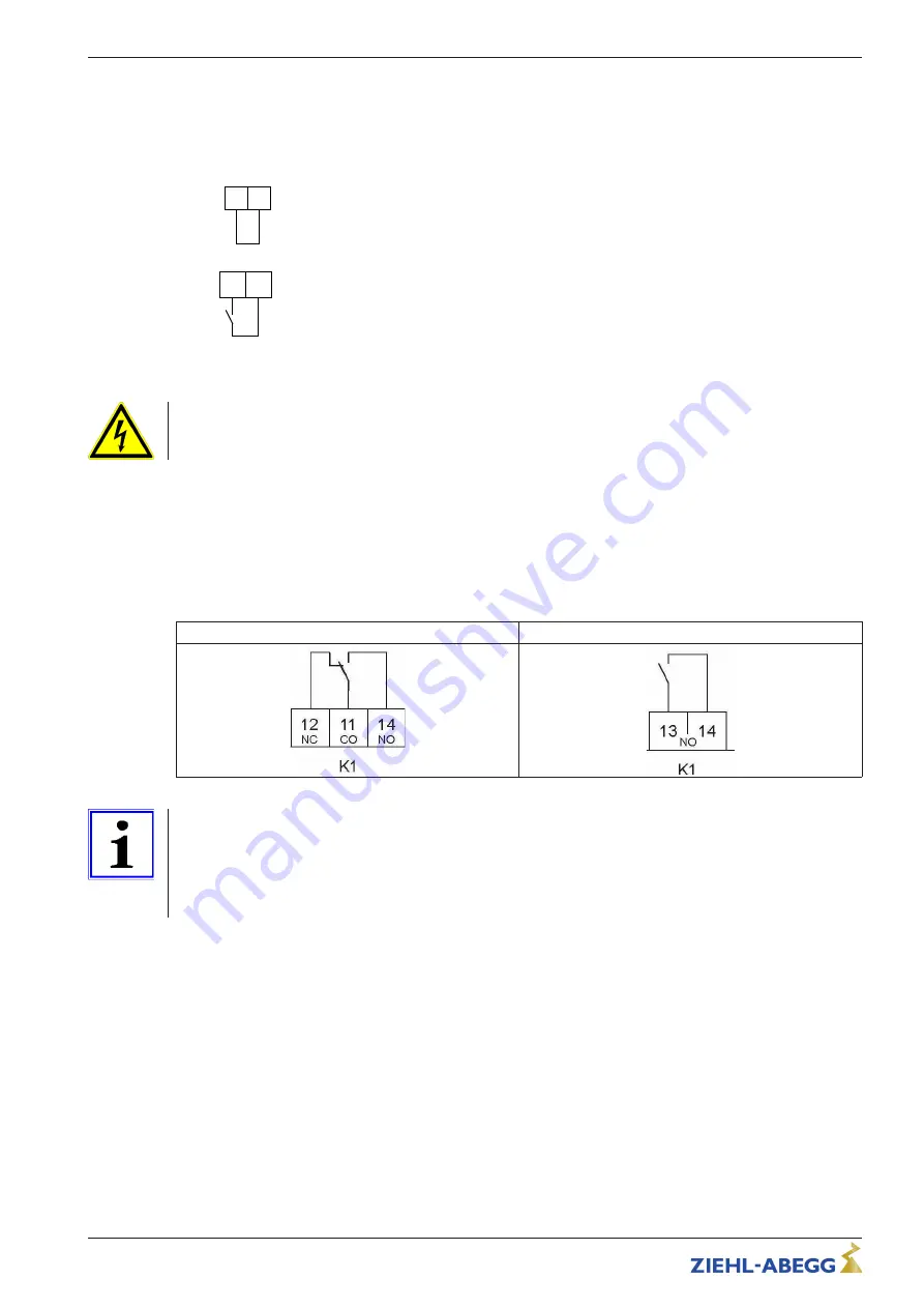
The relay is energised during operation. I.e. on the ECblue BASIC-MODBUS contacts 11-14 are
bridged, and on the ECblue BASIC contacts 13-14. In case of failure, the relay is de-energised (see
Diagnostics/Faults).
Changeover contact for ECblue BASIC-MODBUS
NO contact in ECblue BASIC
Information
After switching on the line voltage, an initialisation time of a maximum 7.5 seconds is required for the
device's electronics to be operational. Subsequently, a reliable status message will be possible. If no
malfunction is detected, the relay will be energised after the initialisation time.
Since both line voltage
fl
uctuations and ambient conditions affect the initialisation time, a different
delay might occur in individual cases.
Assembly instructions
ECblue BASIC-MODBUS, ECblue BASIC
Electrical installation
L-BAL-F079D-GB 2044 Index 002
Part.-No.
31/80

