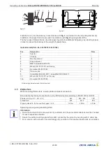
5.14.1
Automatic addressing
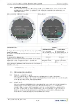
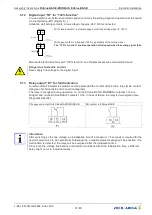
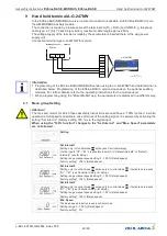
Automatic addressing can be started when the connections
“
ID1
”
and
“
ID2
”
for
“
Addressing
”
are
connected with each other additionally next to the bus connection. I.e. it is no longer necessary to
address every user manually in the network.
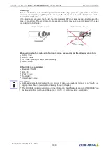
Connection at terminal device via the terminals: A (D+), B (D-) and GND.
Connection of the Slave members via the termials: A (D+), B (D-), GND und ID1 / ID2
Information
•
Except the data link
“
A (D+)
”
,
“
B (D-)
”
the
“
ID1 - ID2
”
and the
“
GND
”
connection may no further cable
cores of the data line be used.
•
The connections for the automatic addressing
“
ID1
”
and
“
ID2
”
are not directly connected electrically
with each other. These may not be bridged; any order of connection is possible.
•
If a repeater is necessary and automatic addressing should be carried out, only the repeater of the
Z-G-1NE type can be used, only it can relay the addressing signal.
•
Maximum number of members in automatic addressing:
–
With hand held terminal type A-G-247 and control unit NETcon type A-G-102ANE max.
63
members.
–
With control module UNIcon MODBUS master type CXE/AV(E) and CXG-24AV(E) a max.
32
participants.
–
With control module UNIcon MODBUS master type CXG-327AN(E)-R a max.
62
participants for
interface 1 and a max.
62
participants for interface 2.
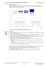
On the
fi
rst user that is connected directly to a terminal, MODBUS Master or PC,
“
GND
”
and
“
ID1
”
or
“
ID2
”
must be bridged. This is recognised as a result and occupied by address
1
.
For the following users the connection
“
ID1
”
or
“
ID2
”
of a user respectively is connected with
connection
“
ID1
”
or
“
ID2
”
of the next user.
The automatic addressing of other users is initiated by the previous user via this connection.
Assembly instructions
ECblue BASIC-MODBUS, ECblue BASIC
Electrical installation
L-BAL-F079D-GB 2044 Index 002
Part.-No.
34/80

