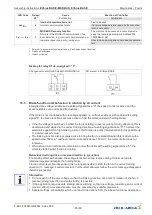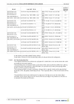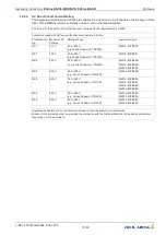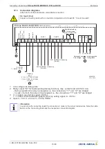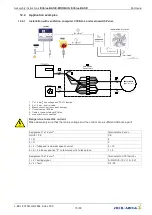
LED Code
Relays
K1*
Cause
Explanation
Reaction of Controller
Adjustment
8 x
–
0
Intermediate circuit overvoltage
If the DC-link voltage increases above a speci
fi
ed
limit, the motor will switch off.
Reason for excessively high input voltage or alter-
nator motor operation.
If the DC-link voltage drops below the limit within
75 seconds, then the cotroller will attempt to start.
Should the DC-link voltage stay above the limit for
more than 75 seconds, the device will switch off
with a fault message.
9 x
–
1
Cooling down period power module
Cooling down period power module for approx.
70 sec.
Final shutoff after 2 cooling-off intervals see code
6.
Power module cooling down period for approx.
70 sec.
Final shutoff after 2 cooling-off intervals see code
6.
10 x
–
0
Communication fault
If the communication watchdog is active, it signals
that MODBUS communication is interrupted.
Response dependent on set watchdog mode (see
MODBUS communication description).
Check MODBUS communication.
11 x
–
0
Error motor start
If a starting command is given (enable available
and Setpoint > 0) and the motor does not start to
turn in the correct direction within 5 minutes, then
an error message will appear.
If it is possible to start the motor in the target
direction of rotation after the error message, the
error message will disappear
Should a voltage interruption occur in the mean-
time, the time taken up to the switch off will begin
again.
Check whether the motor can rotate freely (with-
out line voltage).
Check if the fan is driven in reverse direction by
an air stream (see behaviour in rotation by air
current in reverse direction).
12 x
–
0
Line voltage too low
If the DC-link voltage drops below a speci
fi
ed limit
the device will switch off.
If the line voltage rises above a speci
fi
ed limit
within 75 seconds, then the controller will attempt
to start.
Should the line voltage stay below the speci
fi
ed
limit for more than 75 seconds, the device will
switch off with an error message.
13 x
–
0
Line voltage too high
Cause to high input voltage
If the line voltage increases above a speci
fi
ed
limit, the motor will switch off.
If the line voltage drops below the speci
fi
ed limit
within 75 seconds, then the controller will attempt
to start.
Should the line voltage stay above the speci
fi
ed
limit for more than 75 seconds, the device will
switch off with an error message.
14 x
–
0
Error peak current
If the motor current increases above the speci
fi
ed
limit (even in a short time-frame) the device will
switch-off.
After a switch off the controller waits for 5 seconds
then the controller attempt a start.
Arises within 60 sec. in series 5 further disconnec-
tions a
fi
nal switch off with fault indication follows.
Should no further switch off be exceeded in
60 sec. the counter will be reset.
17 x
–
0
Temperature alarm
Excess of the max. permissible inside tempera-
ture.
Controller switches off motor. Automatic restarting
after cooling down.
Check installation of the device and cooling of the
controller.
18 x
–
0
System error
Device has detected a system error. Only limited
operation, or no operation at all, is possible.
The error is displayed immediately. The motor is
switched off depending on the system error.
Reset by disconnecting the voltage supply. If the
error message persists, repair by the manufac-
turer is necessary.
20 x
–
0
a) Vibration values
If the vibration velocity rises above the speci
fi
ed
limits, an error message is issued.
The error is displayed after the set time. The de-
vice continues to operate unchanged.
Check the impeller for damage, contamination or
ice formation.
b) Lifetime
If the remaining service determined life falls below
the de
fi
ned limit, an error message is issued.
The error is displayed immediately. The device
continues to operate unchanged.
After consultation with the manufacturer, perform
maintenance.
Assembly instructions
ECblue BASIC-MODBUS, ECblue BASIC
Diagnostics / Faults
L-BAL-F079D-GB 2044 Index 002
Part.-No.
64/80

