AP00003A
12.11.2019
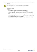
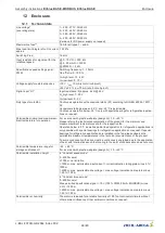
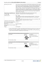
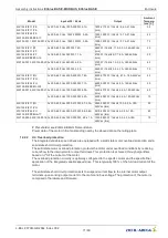
24V 10V GND D1
E1
D
C
O
u
t
(I
m
a
x
=
7
0
m
A
)
D
C
O
u
t
(I
m
a
x
=
1
0
m
A
)
D
ig
it
a
l
In
An
a
lo
g
I
n
L3/N
L2
L1
L1
L2
L3
L1
N
ECblue BASIC
100%-function
(_ _ _ _ _-_I_.D_._ _ _ _), (_ _ _ _ _-_I_.G_._ _ _ _)
K1
Netzspannung
Leistungsschild
Line voltage
Rating-plate
+
2
1
13
14
Kontaktbelastung
Contact rating
max. AC 250 V 2 A
PE
PE
NO
AM-..
3
Eingang
Input
0...10 V / 0...100 % PWM
10...0 V / 100...0 % PWM
4...20 mA
5
0 = 100 %
1 = Auto 0...100 %
4
0 1
1
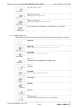
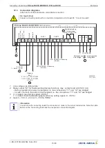
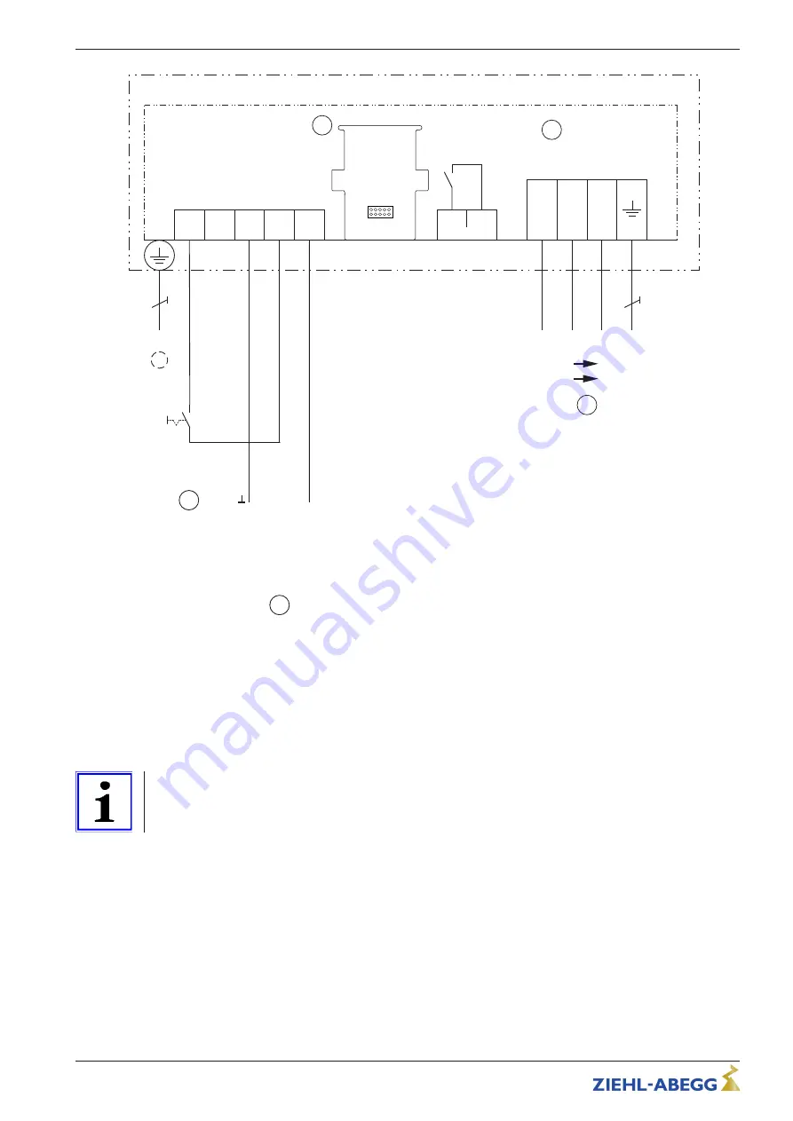
Line voltage see rating plate
2
Relay output "K1" for fault reporting (factory function), max. contact load AC 250 V 2 A)
- During operation the relay is energised, i.e. the connections "13" and "14" are bridged
- In case of a fault, the relay is de-energised
3
Slot for AM-add-on module
4
0 = contact open full fan speed (100 %)
1 = contact closed automatic speed control by setting signal (0...100 %)
5
Input 0...10 V, 4...20 mA
, 0...100 % PWM
Information
In versions with connecting leads the connection is made to the colour coded wires. Note the cable
bands on the connecting leads and the respective connection diagram.
Assembly instructions
ECblue BASIC-MODBUS, ECblue BASIC
Enclosure
L-BAL-F079D-GB 2044 Index 002
Part.-No.
74/80

