screw locking. Permissible tightening torque: M4 = 2.1
Nm; M6 = 9.5 Nm; M10 = 40 Nm; M12 = 70 Nm; related
to friction coef
fi
cient according to DIN EN ISO 4014
µ
tot
= 0.12
–
Motor frame size
068
: comply with stated length of
thread engagement
–
Fans design Q with plastic wall plate:
Use U-plates
DIN 125 to secure. Starting torques allowed: M8 = 10
Nm; M10 = 21 Nm
–
ZAplus fans Type ZC, ZF, ZG, ZN
: When mounting
ZAplus, ensure plastic-compliant connectors.
If
fl
at washers as per DIN EN ISO 7089 or DIN125 are
used for fastening, a permissible torque for Strength
class 8.8 and a frictional value
μ
tot=0.12 of
M8 = 12
–
Nm / M10 =24 Nm / M12 = 40 Nm
is recommended.
Since the concrete bolt or screw varies by customer
unit, these recommendations must be checked for each
respective situation.
Tighten the grate connector with 6Nm torque.
Secure the cable covering against loss after connecting
the motor by securing with 2 cable ties.
For a version with a square rear wall (design Q),
removal of this square plastic plate is prohibited.
•
The following applies to all fan designs:
–
Avoid structural damage or stress with installation.
Make sure the surface is
fl
at and even.
–
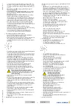
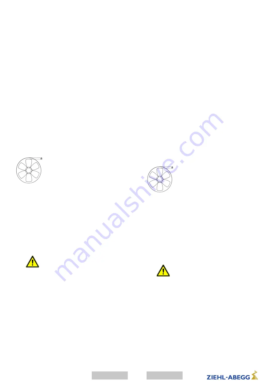
Ensure that the clearance (gap) "a" see
fi
g. between the
fan impeller and the stationary housing section is
constant. Distortion due to uneven surface may lead to
fan failure.
–
Protective measures must be taken against falling parts
when mounting with a hanging rotor.
–
In the case of a vertical motor axis, the respective lower
condensation drain hole must be open (does not apply
to protection class IP55 fans).
–
Motor frame size
068
: The condensation drain-holes
are attached dependent on the installation position or
application. Please supply information about this in the
product-speci
fi
c ordering texts. Make sure the conden-
sation drain-holes are not blocked!
–
Connect fan only to electrical circuits that can be
disconnected with an all-pole isolating switch.
–
Electrical connection corresponding to connection
diagram a) in terminal box b) by cable design connec-
tion diagram on cable or on wall ring.
–
Do not use metal compression-gland
fi
ttings with plastic terminal boxes. - Danger
of an electric shock if connection is not
made correctly!
–
Use a dummy plug seal for the compression-gland
fi
tting as well.
–
When opening cable glands on the fan/motor, check the
condition of the threaded connections and seals.
Always replace defective or brittle threaded connections
and seals.
–
Only use lines which can guarantee a permanent seal
around the cable glands (pressure-resistant, dimension-
ally-stable, round-centred jacket; e.g. by means of
gusset
fi
lling)!
–
Depending on the type of cable gland, attach a water
drain sleeve or use a sealing compound.
–
Screw on plastic terminal box covers should be sealed
with sealant.
–
Starting torque for screw on covers, Plastic version 1.3
Nm, Metal version 2.6 Nm
–
Secure fan connection cable with cable fasteners or
cable clips.
•
Depending on the model the motors
เป
นไปตามมาตรฐานและข
อก
ํ
าหนดต
าง
ๆ
(DIN EN ISO 12100
/ 13857)
–
พัดลมแบบ
A
ในการติดให
ใช
สกรูที่มีระดับความแข็ง
8.8
ที่ขอบมอเตอร
ด
านที่มั่นคง
โดยใช
การล็อคเกลียวที่เหมาะสม
แรงบิดในการขันที่ใช
ได
: M4 = 2.1 Nm; M6 = 9.5 Nm;
M10 = 40 Nm; M12 = 70 Nm;
เกี่ยวกับสกรูตาม
DIN EN
ISO 4014
ค
าสัมประสิทธิ์ความเสียดทาน
µ
ทั้งหมด
= 0.12
–
ขนาดของมอเตอร
068
ให
ขันสกรูถึงระดับความลึกที่ก
ํ
าหนด
–
พัดลมแบบ
Q
ที่มีแผ
นวงแหวนติดก
ํ
าแพงจากพลาสติก
:
ใช
แผ
น
DIN 125
ในการติด
แรงบิดในการขันที่ใช
ได
: M8
=
10 Nm; M10 = 21 Nm
–
พัดลม
ZAplus
ประเภท
ZC, ZF, ZG, ZN
:
ในขณะท
ํ
าการประกอบ
ZAplus
ให
ระมัดระวังการขันเกลียวให
เหมาะสมกับพลาสติก
ถ
าใช
แผ
นแบนตาม
DIN EN ISO 7089
หรือ
DIN125
ในการยึด
แนะน
ํ
าให
ใช
แรงบิด
ในการหมุนที่อนุญาตในประเภทความแข็งแกร
ง
8.8
และที่ค
าความเสียดทาน
μ
ges=0.12
ของ
M8 = 12
–
Nm / M10 =24 Nm / M12 = 40 Nm.
เนื่องจากการขันเกลียวในความเป
นจริง
จะแตกต
างกันตามอุปกรณ
ของลูกค
า
จึงต
องตรวจสอบค
ํ
าแนะน
ํ
านี้ในแต
ละสถานการณ
ขันข
อต
อเกลียวของตะแกรงด
วยแรงบิด
6Nm
ป
องกันรางครอบสายเคเบิลหลังต
อมอเตอร
ด
วยสายรัดเคเบิล
2
เส
น
ในรุ
นที่มีแผงด
านหลังเป
นรูปสี่เหลี่ยมจัตุรัส
(
รูปแบบ
Q)
ไม
ให
ถอดประกอบแผ
นพลาสติกสี่เหลี่ยมจัตุรัสนี้
•
ส
ํ
าหรับพัดลมทุกแบบ
:
–
อย
าติดตั้งให
แน
น
บริเวณที่ติดตั้งต
องราบเรียบ
–
ให
รักษาช
องว
าง
"a"
ให
เท
ากันตามภาพ
ความตึงที่เกิดจากพื้นผิวที่ไม
ราบเรียบ
อาจท
ํ
าให
เกิดริ้วที่ใบพัด
จนท
ํ
าให
พัดลมไม
ท
ํ
างาน
–
ในการติดตั้งด
วยโรเตอร
แบบแขวน
ต
องมีมาตรการป
องกันเพื่อรองรับชิ้นส
วนที่ตกหล
น
–
กรณีแกนมอเตอร
แนวดิ่ง
รูส
ํ
าหรับน้
ํ
าควบแน
นด
านล
างจะต
องเป
ดไว
(
ใช
ไม
ได
กับพัดลมชนิดการป
องกัน
IP55)
–
ขนาดของมอเตอร
068
:
การเจาะรูส
ํ
าหรับน้
ํ
าที่ควบแน
นขึ้นอยู
กับต
ํ
าแหน
งการติดตั้ง
หรือลักษณะการใช
งาน
โดยข
อมูลที่เกี่ยวข
อง
มีอยู
ในข
อความการสั่งซื้อผลิตภัณฑ
แต
ละชนิด
โปรดระวังว
ารูส
ํ
าหรับน้
ํ
าควบแน
นจะต
องไม
ป
ด
!
–
อนุญาตให
ติดตั้งพัดลม
ในวงจรไฟฟ
าที่ป
ดได
โดยใช
สวิตซ
แยกทุกขั้วเท
านั้น
–
การเชื่อมต
อกระแสไฟฟ
าตามแผนผังวงจร
a)
ในกล
องเทอร
มินอล
b)
ในขณะเดินสาย
แผนผังวงจรที่สายหรือวงแหวนติดก
ํ
าแพง
–
ไม
ใช
ข
อต
อเกลียวที่เป
นโลหะ
ในกล
องเทอร
มินอลพลาสติก
อาจเกิดไฟฟ
าช็อตได
เมื่อต
อไม
ถูกต
อง
!
–
ใช
ซีลของจุกป
ดส
ํ
าหรับข
อต
อเกลียวด
วย
–
ขณะเป
ดข
อต
อเกลียวสายเคเบิลที่พัดลม
/
มอเตอร
ให
ตรวจสอบสภาพของข
อต
อเกลียวและซีลต
าง
ๆ
ต
องเปลี่ยนเกลียวและซีลที่ช
ํ
ารุดหรือเปราะบาง
–
ให
ใช
เฉพาะสายเคเบิล
ที่มีการป
องกันการรั่วซึมแบบถาวรในข
อต
อสาย
(
ปลอกหุ
มชนิดทรงกลมตรงกลาง
ที่มีรูปทรงเสถียรและทนต
อแรงกด
เช
น
โดยการใช
สารตัวเติม
)!
–
ขึ้นอยู
กับประเภทของทางเข
าสายเคเบิล
ให
มีทางโค
งให
น้
ํ
าไหลหรือใช
สารอุดรอยรั่ว
–
ให
อุดข
อต
อเกลียวของฝาในกล
องเทอร
มินอลพลาสติกเพิ่มด
วยสารอุดรอยรั่ว
–
แรงบิดในการขันส
ํ
าหรับข
อต
อเกลียวของฝา
:
รุ
นพลาสติก
1.3
Nm,
รุ
นโลหะ
2.6 Nm
–
ยึดสายเคเบิลเชื่อมต
อของพัดลมด
วยตัวยึดสายเคเบิล
หรือตัวรัดสายเคเบิล
•
ตามแต
ละรุ
น
มอเตอร
จะ
3
ภาษาไทย
english
00280311-D-T
L-BAL-001-T-1939-Index
018

