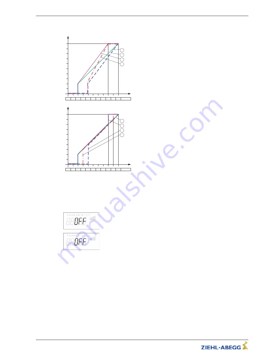
Example for Mode
“
1.01
”
with speed setting signal 0 - 10 V
[Hz]
Si E
0
1
2
3
4
5
6
7
8
9
10
0 – 10 V
24.09.2009
v_e1_modus_1_hz.vsd
1
Modus 1
E1 min. = 0 %, E1 max. = 100 %
50
2
E1 min. = 20 %, E1 max. = 100 %
40
30
20
10
3
E1 min. = 20 %, E1 max. = 80 %
E1 min. = 0 %, E1 max. = 80 %
4
Modus 1
Example:
“
E1 min.
”
= 20 %
The controller begins only at approx. 20% higher
signal with minimal modulation.
Example:
“
E1 max.
”
= 80 %
The modulation rises linear to 100% modulation
with 80% setting signal.
[Hz]
Si E
0
1
2
3
4
5
6
7
8
9
10
0 – 10 V
24.09.2009
v_e1_modus_2_hz.vsd
1
Modus 2
E1 min. = 0 %, E1 max. = 100 %
50
2
E1 min. = 40 %, E1 max. = 100 %
40
30
20
10
3
E1 min. = 30 %, E1 max. = 90 %
E1 min. = 0 %, E1 max. = 80 %
4
Modus 2
Example:
“
E1 min.
”
= 30 %
Only with approx. 30 % setting signal the controller
begins with approx. 30% modulation.
Example:
“
E1 max.
”
= 80 %
Over 80 % setting signal the modulation is switched
to 100 % modulation.
Idealized principle diagrams for setting:
“
Min. Speed
”
= 0.0 Hz and
“
Max. Speed
”
= 50.0 Hz
9.10.3.2
Inverting analog inputs
“
E1
”
/
“
E2
”
After programming the signal or sensor type, an inversion of the inputs can be carried out.
E1 Inverting
Factory setting for Inverting inputs =
“
OFF
”
(if input activated) (signal: 0 - 10 V, 0 -
20 mA, 4 - 20 mA).
For activation using inverted default signals or sensors with inverted output signals
proportional to the measurement range, switch inverting to
“
ON
”
(Signal: 10 - 0 V, 20 -
0 mA, 20 - 4 mA).
E2 Inverting
Operating Instructions
Fcontrol
–
model series FXDM
Programming
L-BAL-E072-GB 1642 Index 008
Part.-No.
68/105


