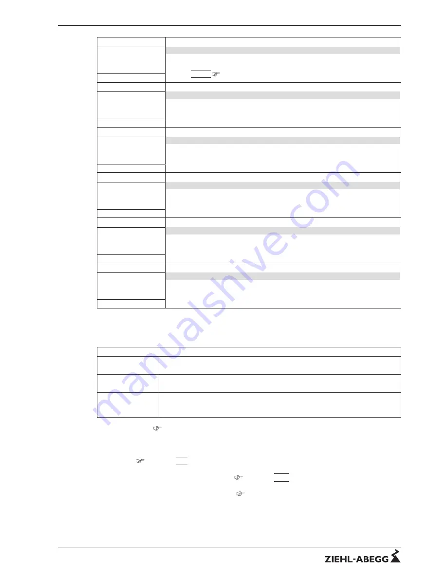
Setting
2.Setpoint 2
Setpoint 2 for control circuit 2
Setting
“
Setpoint 2
”
e.g. reduced value for night operation.
Switch over Setpoint 1/2 by external contact (as long as no allocation is carried out:
Display:
|
- - - - -
|
IO Setup).
- - - - -
2.Setpoint 2
Setting
2. Pband 1
Pband 1 for control circuit 2
Setting range: in measuring range of sensor
Factory setting: 5,0 bar
5.0 bar
2. Pband 1
Setting
2. Min. Speed
Minimal Speed for control circuit 2
Setting range: 0. rpm...
“
2. Max. Speed
”
Factory setting: 0 %
0 %
2. Min. Speed
Setting
2. Max. Speed
Maximal Speed for control circuit 2
Setting range: 100 %...
“
2. Min. Speed
”
Factory setting: 100 %
100 %
2. Max. Speed
Setting
Manual mode
Manual mode for control circuit 1
“
OFF
”
= automatic control as function of the set parameters (Factory setting)
“
ON
”
= automatic control without function, speed setting in menu
“
Speed manual
”
OFF
1. Manual mode
Setting
Speed Manual mode
Speed Manual mode for control circuit 1
Setting range: 0 rpm...
“
1. Max. Speed
”
Factory setting: 100 %
100 %
1. Speed man.
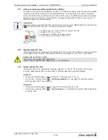
Function extension for digital inputs
“
D1
”
and
“
D2
”
in operation with second control circuit
D1 / D2 Function
Description *
E1 / E2
(4D)
The output for the control circuit 2 is placed at the speci
fi
ed motor output, in addition to
“
A1
”
. Control circuit 1 has no output for the duration of the switching.
2. Setpoint 1/2
(9D)
for control circuit 2: Switch over
“
Setpoint 1
”
/
“
Setpoint 2
”
2.Setp+Pband1/2
(16D)
for control circuit 2: Switch over Setpoint 1/2 and Pband 1/2
When programming this function,
“
Setting
”
additionally lists the parameter:
“
2.Pband 2 for
control circuit 2.
”
*
Detailed description
IO Setup / Digital Inputs
“
D1
”
/
“
D2
”
Following restrictions apply for the control circuit 2:
•
The
“
Manual Mode
”
function in the
“
Setting
”
menu group only in
fl
uences control circuit 1!
•
The Limit (
IO Setup
|
3D
|
and Controller Setup) function in
fl
uences both control circuits simulta-
neously.
•
The
“
Max. Speed
”
setting by a digital input (
IO Setup
|
11D
|
) simultaneously in
fl
uences both
control circuits. I.e. at
“
1.Max. Speed
”
and at
“
2.Max. Speed
”
.
•
The controller con
fi
gurations (KP, KI, KD, TI
Controller Setup) are identical for both control
circuits. Fine adjustment is possible for each control circuit by the separate
“
Pband
”
setting.
Operating Instructions
Fcontrol
–
model series FXDM25/32AM
Base setup
L-BAL-E212-GB 1451 Index 003
Part.-No.
27/123


