background image

2.5 Start-up and during operation

Attention!

During commissioning, unexpected and hazardous conditions can arise in the

entire installation due to defective adjustments, defective components or incorrect

electrical connections. Remove all persons and objects from the hazardous area.

During operation, the device must be closed or installed in a control cabinet.

Fuses may only be replaced by new ones and must not be repaired or bypassed.

The data for the maximum line fuse are to be considered absolutely (

Technical

data). Use only fuses speci

ed in schematic diagrams.

Any faults detected in the electric system/modules/operating equipment must be

corrected immediately. If these faults are not corrected, the device/system is

potentially very dangerous. The device/system must therefore not be operated

when it is faulty.

Pay attention to smooth, low vibration running of the motor/fan, the appropriate

instructions in the drive documentation must be observed!

2.6 Work on the device

Information

Mounting, electrical connection, and start-up operation may only be carried out by

an electrical specialist in accordance with electrotechnical regulations (e.g. DIN

EN 50110 or DIN EN 60204)!

Danger owing to electric current

It is forbidden to carry out work on electrically live parts. Protection class of the

device when open is IP 00! It is possible to inadventently touch components

carrying hazardous voltages.

The safe isolation from the supply must be checked using a

two-pole

voltage detector.

Attention!

Automatically restart after a power failure or mains disconnection!

2.7Modi

cations / interventions in the device

Attention!

For reasons of safety, no unauthorized interventions or modi

cations may be made on

the device. All planned modi

cations must be authorized by the manufacturer in writing.

Use only genuine spare parts / genuine wearing parts / genuine accessories from Ziehl-

Abegg.These parts were speci

cally designed for the device. There is no guarantee that

parts from non-original sources are designed and manufactured in correspondence with

load and safety requirements.

Operating Instructions

NETcon

model series DIG-9NE

Safety instructions

L-BAL-E134-GB 1118 Index 001

Part.-No. 00163363-GB

6/21

Summary of Contents for NETcon DIG-9NE

Page 1: ...NETcon DIG 9NE Part No 380075 MB TCP Gateway Operating Instructions Software version from version D2092A01 and D2092B02 L BAL E134 GB 1118 Index 001 Part No 00163363 GB english...

Page 2: ...e device 6 2 8 Operator s obligation of diligence 7 2 9 Employment of external personnel 7 3 Product overview 7 3 1 Operational area 7 3 2 Function 7 3 3 Maintenance 8 3 4 Transport 8 3 5 Storage 8 3...

Page 3: ...work with Proxy Server 15 6 5 Addressing with MODBUS TCP IP 16 6 6 Debug mode 16 6 7 MODBUS Timeout 17 7 Network overview 18 8 Enclosure 19 8 1 Technical data 19 8 2 Connection diagram 20 8 3 Dimensio...

Page 4: ...escribed hardware and software in the device has been examined It is still possible that non compliances exist no guarantee is assumed for complete conformity To allow for future developments construc...

Page 5: ...nforms to the state of the art at the time of delivery and is fundamentally considered to be reliable The device and its accessories must only be used in a awless condition and installed and operated...

Page 6: ...lectrical connection and start up operation may only be carried out by an electrical specialist in accordance with electrotechnical regulations e g DIN EN 50110 or DIN EN 60204 Danger owing to electri...

Page 7: ...ces attached to the device are never removed and remain legible 2 9 Employment of external personnel Maintenance and service work are frequently carried out by external employees who often do not reco...

Page 8: ...riods we recommend a maximum of one year 3 6 Waste disposal recycling Disposal must be carried out professionally and environmentally friendly in accordance with the legal stipulations 4 Mounting 4 1...

Page 9: ...using cover removed is prohibited because energized exposed parts are present inside the device Disregarding this regulation can lead to severe personal injury The required protective earth connection...

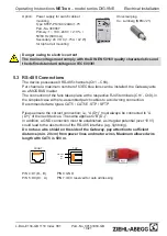
Page 10: ...s Ch1 Ch9 in the simplest case with pre assembled patch cables to avoid wrong connection Recommended wire types CAT5 CAT5E STP SFTP Please ensure the correct connection i e A D must always be connecte...

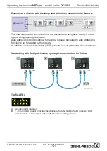
Page 11: ...ter In addition a network termination 150 should be used at the end of every channel Networking with RJ45 patch cable by usage connection box for ECblue 11 04 2011 v_modbus_net_autoadr_gateway vsd 4 6...

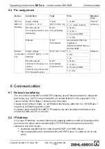
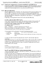
Page 12: ...the NETcon MB TCP Gateway at an Ethernet network is made with patch lines e g CAT5 to the shielded RJ 45 socket present on the equipment The rules of wiring 10 100 Base T networks are to be kept Usual...

Page 13: ...perties Choose Use the following IP address and enter for example these values IP Address 192 168 1 x For x enter a number between 1 and 254 Subnet mask 255 255 255 0 Gateway With WLAN the address of...

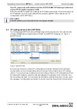
Page 14: ...Chips is implemented in the NETcon MB TCP Gateway gure 1 CHIPTOOL Figure 1 CHIPTOOL Now choose the device whose IP con guration should be changed Click with right mouse button on the corresponding row...

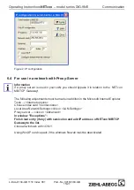
Page 15: ...r Tools Internet options Choose index card Connections Local Area Network Settings click on LAN Settings Proxy server click on Advanced In window Exceptions Finish last entry if any with semicolon and...

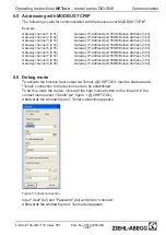
Page 16: ...Gateway IP Address port 507 MB slave Address 1 63 Gateway channel 8 Ch8 Gateway IP Address port 508 MB slave Address 1 63 Gateway channel 9 Ch9 Gateway IP Address port 509 MB slave Address 1 63 6 6 D...

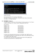
Page 17: ...el 3 TIMEOUT1 500 Timeout channel 4 TIMEOUT1 500 Timeout channel 5 TIMEOUT1 500 Timeout channel 6 TIMEOUT1 500 Timeout channel 7 TIMEOUT1 500 Timeout channel 8 TIMEOUT1 500 Timeout channel 9 If a node...

Page 18: ...it 16xTX unmanaged Modbus RTU RS485 CAT5 STP max 500m Ethernet Standard CAT5 max 100m 3 1 2 9 Modbus channels per Gateway 150 Ohm Max 63 FFU 150 Ohm Max 63 FFU 150 Ohm Max 63 FFU 9 150 Ohm Max 63 FFU...

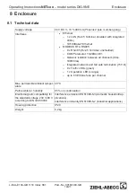
Page 19: ...ermination 150 9 x Traf c LEDs green 1 x Operation LED orange up to 63 ECblue fans per channel Max permissible ambient temper ature 40 C Permissible rel humidity 85 no condensation Electromagnetic com...

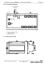
Page 20: ...J45 RJ45 RJ45 RJ45 RJ45 RJ45 ohne Funktion without function Ch1 Ch2 Ch3 Ch4 Ch5 Ch6 Ch7 Ch8 Ch9 RJ45 RJ45 RJ45 DIG 9NE 1 2 3 1 Connection Supply voltage 2 RS 485 channel 3 Ethernet connection 8 3 Dime...

Page 21: ...STE support department for control systems ventilation technol ogy Our worldwide contacts are available in our subsidiaries for deliveries outside of Ger many www ziehl abegg com If you make returns f...

Reviews: