Handbook
Ucontrol
type-lines PXDM
Date 06/04
TBL02_55-GB06/04
Part.-No. 00153239-GB
Page 105 / 105
14.5 Index
A
Address ................................................................................. 91
Air velocity control ................................................................. 67
alarm sensors........................................................................ 74
Alarms ................................................................................... 24
Analog Output ....................................................................... 81
application examples ............................................................. 25
Average calculation ............................................................... 34
B
base setup............................................................................. 21
C
cable installation.................................................................... 12
collecting fault........................................................................ 84
Connection diagram ............................................................ 101
control function ...................................................................... 78
controller action ..................................................................... 79
controller type........................................................................ 79
Cooling .................................................................................. 37
cosPhi.................................................................................... 97
current-operated circuit-breaker ............................................ 11
D
data bus................................................................................. 16
D-component......................................................................... 79
delivery status ....................................................................... 20
Derating................................................................................. 13
Diagnostic.............................................................................. 99
digital inputs .......................................................................... 83
Dimension sheet.......................................................... 103, 104
DSF2-25 ................................................................................ 44
DSG................................................................................. 52, 60
E
Enable ................................................................................... 84
Error ...................................................................................... 24
Events ................................................................................... 24
External fault ......................................................................... 24
Ex-zones ............................................................................... 15
F
factory setting ........................................................................ 20
frequency converters ............................................................. 14
H
Heating.................................................................................. 37
I
I-component .......................................................................... 79
Inductance............................................................................. 97
input resistance ....................................................................... 9
Integration time...................................................................... 79
isolation ................................................................................. 84
K
K Factor................................................................................. 60
L
Language .............................................................................. 20
LC-Display............................................................................. 17
leakage currents.................................................................... 11
Limit................................................................................. 75, 85
Limits ..................................................................................... 93
line fault ................................................................................. 24
Line fuse.................................................................................. 8
M
MAL ....................................................................................... 67
malfunctions query ................................................................ 24
Menu operation ..................................................................... 18
Messages .............................................................................. 24
minimum rate of air................................................................ 76
MODBUS............................................................................... 16
mode of operation ................................................................. 25
Motor connection................................................................... 14
Motor noise............................................................................ 14
Motor protection .................................................................... 15
motor protection unit.............................................................. 14
N
Network ................................................................................. 91
O
operating mode ..................................................................... 21
outdoor compensation........................................................... 55
Output 0-10 V ........................................................................ 81
Overload................................................................................ 24
P
P-component ......................................................................... 79
period length.......................................................................... 99
PID ........................................................................................ 79
PIN ........................................................................................ 20
Pin protection ........................................................................ 73
Pressure control for condensers............................................ 43
Pressure control for ventilation systems ................................ 51
PTC thermistors .................................................................... 15
R
Rampdown time .................................................................... 97
Rampup time ......................................................................... 97
refrigerant .............................................................................. 45
Relay outputs ........................................................................ 90
Reset............................................................................... 21, 84
Resonances .......................................................................... 98
re-start................................................................................... 21
Reverse ................................................................................. 78
RS-485 .................................................................................. 16
S
Second group ........................................................................ 77
semiconductor fuse ................................................................. 8
Set Intern 2............................................................................ 86
set protection......................................................................... 73
Setpoint 2 .............................................................................. 86
Setpoint decrease ........................................................... 55, 63
Setup..................................................................................... 81
short circuit releasing .......................................................... 102
Signal connection .................................................................. 15
software version .................................................................... 21
speed controller..................................................................... 29
speed reduction..................................................................... 85
Start Temperature ........................................................... 55, 63
supply frequency ................................................................... 99
suppression ........................................................................... 98
T
Technical data ......................................................................... 8
Temperature control .............................................................. 31
Terminal ................................................................................ 16
TF.. ........................................................................................ 32
thermal contacts .............................................................. 14, 15
thermistors............................................................................. 14
Two-wire-technology ............................................................. 15
U
user setting............................................................................ 20
V
Volume control ...................................................................... 59
Summary of Contents for Ucontrol PXDM Series
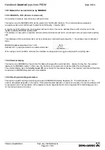
Page 80: ...Handbook Ucontrol type lines PXDM Date 06 04 TBL02_55 GB06 04 Part No 00153239 GB Page 80 105 ...
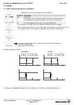
Page 92: ...Handbook Ucontrol type lines PXDM Date 06 04 TBL02_55 GB06 04 Part No 00153239 GB Page 92 105 ...
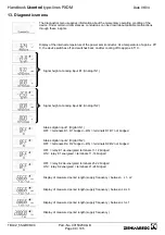
Page 96: ...Handbook Ucontrol type lines PXDM Date 06 04 TBL02_55 GB06 04 Part No 00153239 GB Page 96 105 ...
Page 100: ......

