Handbook
Ucontrol
type-lines PXDM
Date 06/04
TBL02_55-GB06/04
Part.-No. 00153239-GB
Page 89 / 105
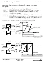
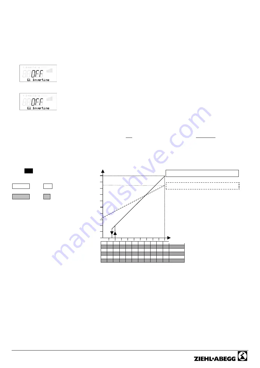
Min.Speed
100 %
50 %
U Motor
Setting signal / Set internal 0-100 %
0
1
2
3
4
5
6
7
8
9
10 0-10 V
10
9
8
7
6
5
4
3
2
1
0 10-0 V
0
2
4
6
8
10
12
14
16
18
20 0-20 mA
20
18
16
14
12
10
8
6
4
2
0 20-0 mA
4
5,6 7,2 8,8 10,4 12 13,6 15,2 16,8 18,4 20 4-20 mA
20 18,4 16,8 15,2 13,6 12 10,4 8,8 7,2 5,6
4 20-4 mA
Min. speed = 0 % Max. Speed = 100 %
Min. speed = 35 % Max. Speed = 85 %
Idealized principle diagram
10.3 Inverting analog inputs E1 and E2
After the hardware adjustments have been carried out through the internal jumpers and programming the signal or sensor
type, an inversion of the inputs can be carried out.
Factory setting for Inverting inputs = “OFF“ (if input activated )
(signal: 0-10 V, 0-20 mA, 4-20 mA)
For activation using inverted default signals or sensors with inverted output signals proportional
to the measurement range, switch inverting to “ON”
(Signal: 10-0 V, 20-0 mA, 20-4 mA)
Ziehl-Abegg sensors generally do not work with inverted output signals
(i.e., these are not suitable for an inverted evaluation)
e. g.:
DSG200
0-10 V
proportional
0-200 Pa
MAL1
0-10 V
proportional
0-1 m/s
DSF2-25
4-20 mA
proportional
2-25 bar
In sensors with inverted outputs, 0 V or 4 mA must correspond to the final value of the
measurement range.
e. g. pressure sensor 10-0 V
proportional
0-200 Pa
example:
mode
1.01
speed controller
setting by external signal
Inverting OFF
Inverting
ON
↓
↑
↓
↑
Summary of Contents for Ucontrol PXDM Series
Page 80: ...Handbook Ucontrol type lines PXDM Date 06 04 TBL02_55 GB06 04 Part No 00153239 GB Page 80 105 ...
Page 92: ...Handbook Ucontrol type lines PXDM Date 06 04 TBL02_55 GB06 04 Part No 00153239 GB Page 92 105 ...
Page 96: ...Handbook Ucontrol type lines PXDM Date 06 04 TBL02_55 GB06 04 Part No 00153239 GB Page 96 105 ...
Page 100: ......


