4.2
Switch cabinet installation
CAUTION!
Warning!
ZArec4C is designed for wall mounting in the machine room or lift shaft. Adequate cooling must be
ensured for assembly in the switch cabinet. The power loss of the ZArec4C (see chapter "Technical
Data") must be taken into account here.
The speci
fi
ed installation position and the minimum distances must be observed when assembling in
the switch cabinet.
4.3
Wall mounting / shaft mounting
4.3.1
ZArec4C 013
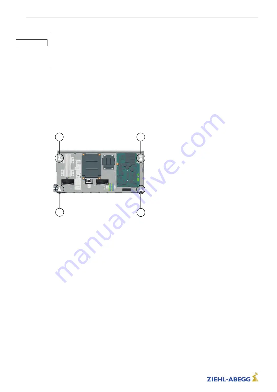
The ZArec4C is mounted on a wall or in a shaft using a 4-point fastening. The ZArec4C 013 is to be
mounted in a horizontal installation position.
"
Mark the positions of the fastening points (see
fi
g.). See the dimension drawings in the "Mechanical
Installation / Dimensions / Minimum Clearances" chapter for the distances between the fastening
points.
1
2
1
2
Fastening points
1
upper fastening points
2
Lower fastening points
"
Drill fastening holes.
"
Attach fastening screws for the fastening points.
"
Hang ZArec4C on the fastening points.
Original operating instructions
ZArec4C
Mechanical installation
R-TBA14_03-GB 1817 Index 007
Part.-No. 00163436-GB
10/64


