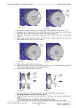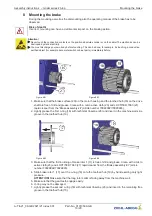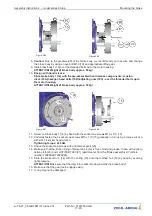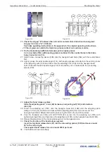
10 Adjustment of the microswitch/inductive proximity switch for re-
lease monitor
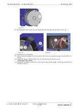
Figure 10-01
Figure 10-02
Adjustment of the microswitches/inductive proximity switches is only necessary if they are not working
correctly.
The microswitches/inductive proximity switches are located on top of the brake (see arrow).
ATTENTION! It must be ensured that the appropriate microswitches/inductive proximity
switches are selected for the magnet to be adjusted.
Adjustment of the release monitor with microswitches/inductive proximity switches, see
“
Assembly
and adjustment of release monitor with microswitches or inductive proximity switches
”
chapter in the
appendix at the original operating instructions.
11 Disposal / recycling
Disposal must be carried out professionally and environmentally friendly in accordance with the legal
stipulations.
Assembly instructions
–
model series ZAtop Adjustment of the microswitch/inductive proximity switch for release
monitor
A-TIA21_08-GB 2021/21 Index 001
Part.-No. 01013509-GB
16/20


