5 Electrical installation
5.1
Safety precautions
Work on electric components may only be carried out by trained electricians or by persons instructed
in electricity under the supervision of an electrician in accordance with electrical engineering regula-
tions.
A second person must always be present when working on energized parts or lines who disconnects
in case of emergency.
Electrical equipment must be checked regularly: Loose connections are to be re-tightened and
damaged cables must be replaced immediately.
Always keep switch cabinets and all electrical supply facilities locked. Access is only allowed for
authorized persons using a key or special tool.
Never clean electrical equipment with water or similar liquids.
5.2
EMC Directive
Compliance with the EMC directive 2014/30/EU only applies to this product if frequency inverters
tested and recommended by ZIEHL-ABEGG SE are used and they are installed in line with the
associated operating instructions and are EMC-compatible. If this product is improperly integrated into
a system or is combined and operated with non-recommended components, the manufacturer or
operator of the complete system is solely responsible for compliance with the EMC
directive 2014/30/EU.
5.3
motor
CAUTION!
"
"
The motor cable for the elevator machine is available as an option.
"
"
The elevator machine may not be connected to the supply voltage without a frequency
inverter.
5.3.1
Cable cross section
The cable cross-section must be speci
fi
ed dependent on the motor current and the ambient conditions
(e.g. temperature, wiring method) in accordance with DIN VDE 0298-4.
5.3.2
Type of cable
Always use shielded cables for the motor connection. Both rigid and
fl
exible cables can be used.
5.3.3
Cable length
The maximum cable length is 25 m. With a motor line
> 25 m
compliance with DIN EN 12015 (Electro-
magnetic Compatibility - Interference emissions) and DIN EN 12016 (Electromagnetic Compatibility -
Interference immunity) can no longer be guaranteed.
5.3.4
Mechanical connection conditions
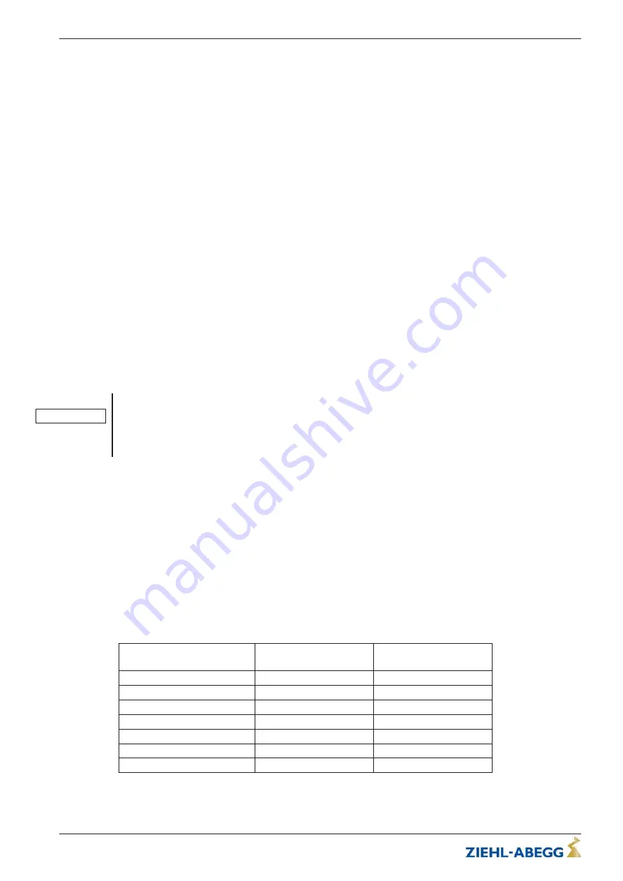
Rated motor current
[A]
Thread size
Terminal board
Thread size
Cable gland
up to 20
M8
M25
> 20 - 35
M8
M32
> 35 - 63
M8
M40
> 63 - 80
M8
M50
> 80 - 100
M10
M50
> 100 - 125
M10
M63
> 125
M12
M63
Table 5-3-4
Original operating instructions
ZAtop
–
model series SM315.100A
Electrical installation
A-TBA22_02-GB 2022/50 Index 002 Part.-No. 01013486-GB (EU-BD 1075)
16/76


