


6. Screw the thermostat (2) into the bearing bracket.
2
7. Guide the connecting cable for the thermostat through the cable gland supplied (item 3).
8. Fit the insulating hose supplied (item 14) on the connecting cable for the thermostat.
9. Insert the insulating hose supplied (item 14) into the cable gland supplied (item 3).
10. Shorten the connecting cable for the thermostat to the desired length and attach the wire end
sleeves.
11. Fit the cover (9).
12. Screw on the terminal box cover with two hexagon head screws (7).
13. Screw on the eyelet (6) with a hexagon head screw (5).
14. Tighten the cable gland supplied (item 3) and the cable glands (8).
5.2
Mounting of the forced ventilation
Information
It is possible that the drive is positioned in such a way that the terminal box for the forced ventilation is
not accessible when the forced ventilation is installed. In this case, the terminal box can also be
installed on the other side of the forced ventilation.
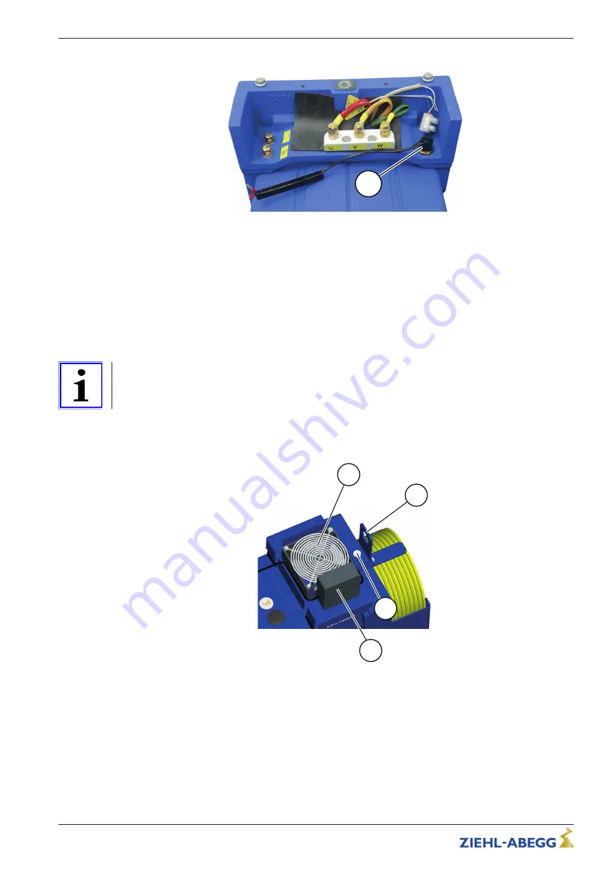
1. Unscrew the hexagon head screw (11) and remove the eyelet (12).
2. Fit the forced ventilation (1).
3. Screw on the forced ventilation (1) and eyelet (12) with the hexagon head screw (11).
11
1
13
12
Assembly instructions
Mechanical installation
A-TIA20_04-GB 2010 Index 001
Part.-No. 01015846-GB
3/4


