SW32V
11820-0701-01
Page
8 / 22
www.ziehl.de
9
Detailed description
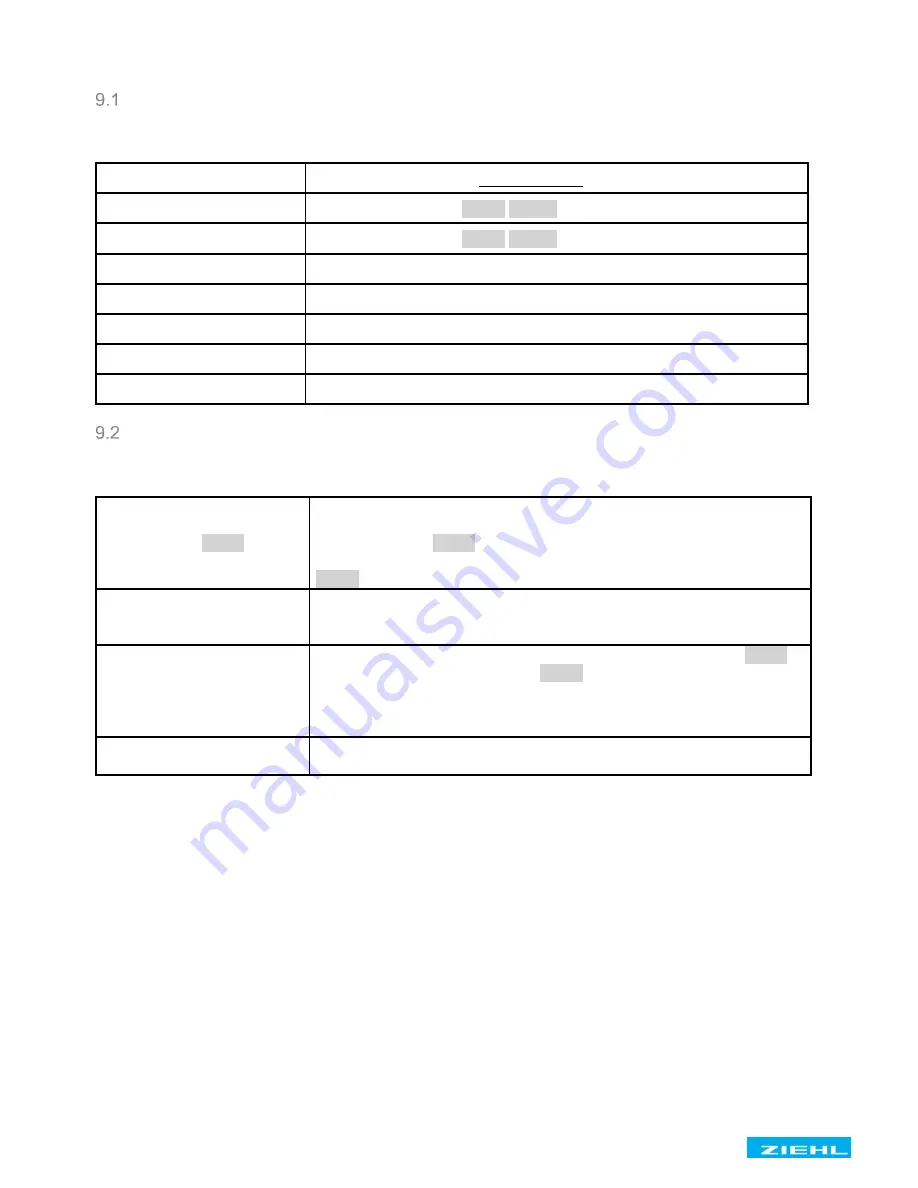
Description of the connections
Connection
Function
A1 and A2
Control voltage Us, see Technical Data
11, 12, 14
Relay K1, menu item
8
A1:
8
,
8
a1_.
8
21, 22, 24
Relay K2, menu item
8
A2:
8
,
8
a2_.
8
nc
Not used
N (-)
Neutral conductor (DC -)
L1 (+)
Phase L1 (DC +)
L2
Phase L2
L3
Phase L3
Functional characteristics
Functional characteristics
Explanation
Display mode
8
Scn
8
In programs with multiple display values, there is a switchover into the
automatic display mode after the last display value, which is indicated
by the display of
8
scn
8
.
All measurements will now be displayed cyclically for the time set in
8
dit
8
.
MIN / MAX values
All min and max values are saved zero-voltage maintained (non
volatile). After triggering, the trip value is still available after the control
voltage is switched off.
Reset delay
After applying the control voltage, for K1 the reset delay set in
8
A1_
8
and for K2 the reset delay set in
8
A2_
8
counts down. All alarms,
excepting during false phase sequence, are suppressed during this
time. During this time, the relay remains dropped out, which excludes
a temporary line fault upon starting.
Reset
Use the Reset key or interrupt the control voltage for > 5 s (comply
with reset delay)


