2 of 9
ZIG-ILC User Manual
UM-003-0001-102-00 | June 09, 2020
© 2020 Zigen Corporation
www.zigencorp.com
Essentials Control
Server
HDMI
AVoIP Ethernet
Facility Ethernet
Facility Ethernet
ZIG-ILC populated with
ZIG-IPPRO-TX and ZIG-
IPPRO-RX (Transmitter)
10GbE Managed
Switch for AVoIP LAN
Network Connection
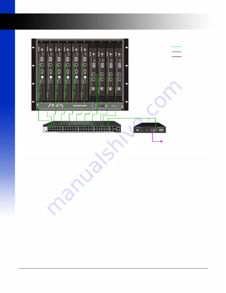
The Example Wiring Diagram,
Figure 1
, shows a typical network connection for an IP-Logic ecosystem. The AVoIP
Ethernet is the 10GbaseT network where all video, audio, and control traffic flows. The network control port of the
ZIG-ILC needs to reside on the same AVoIP LAN to allow the Essentials Control Server to manage and monitor the
operation of the ZIG-ILC. The ZIG-ILC network port can be connected to an open port of the managed switch or to
any ZIG-IPPRO device’s 1G network. The virtual switch function of the ZIG-IPPRO allows any 1G connected device
to participate in the AVoIP network as long as the ZIG-IPPRO’s 10G network (copper or optical) is connected to the
AVoIP LAN.
Installation
Install the ZIG-ILC to an open 8U rack mount system. It is important not to block any ventilation ingress or egress
of the ZIG-ILC.
Determine the ZIG-IPPRO units that will be installed in the ZIG-ILC. Remove the required blank cover plates in front
of the ZIG-ILC. To allow optimized cooling of all installed ZIG-IPPRO devices, it is important not to leave any open
slots uncovered. Install the included blank cover plates as required.
Install the appropriate ear mounts (included) to the ZIG-IPPRO-RX and/or ZIG-IPPRO-TX units (refer to
Figure 2
).
The Transmitters are wider than the Receivers so use the narrower ear mounts for the Transmitter units.
After installing the ear mounts to the ZIG-IPPRO devices, mount the assembly from the front of the ZIG-ILC (refer
to
Figure 3
). Tighten the Thumb Screws to secure the assembly.
Installation
Figure 1. Example Network Diagram


