ZGR TOWER PRO 6 10 KVA
Operation manual
www.zigor.com
18
Parallel installation steps as below:
1)
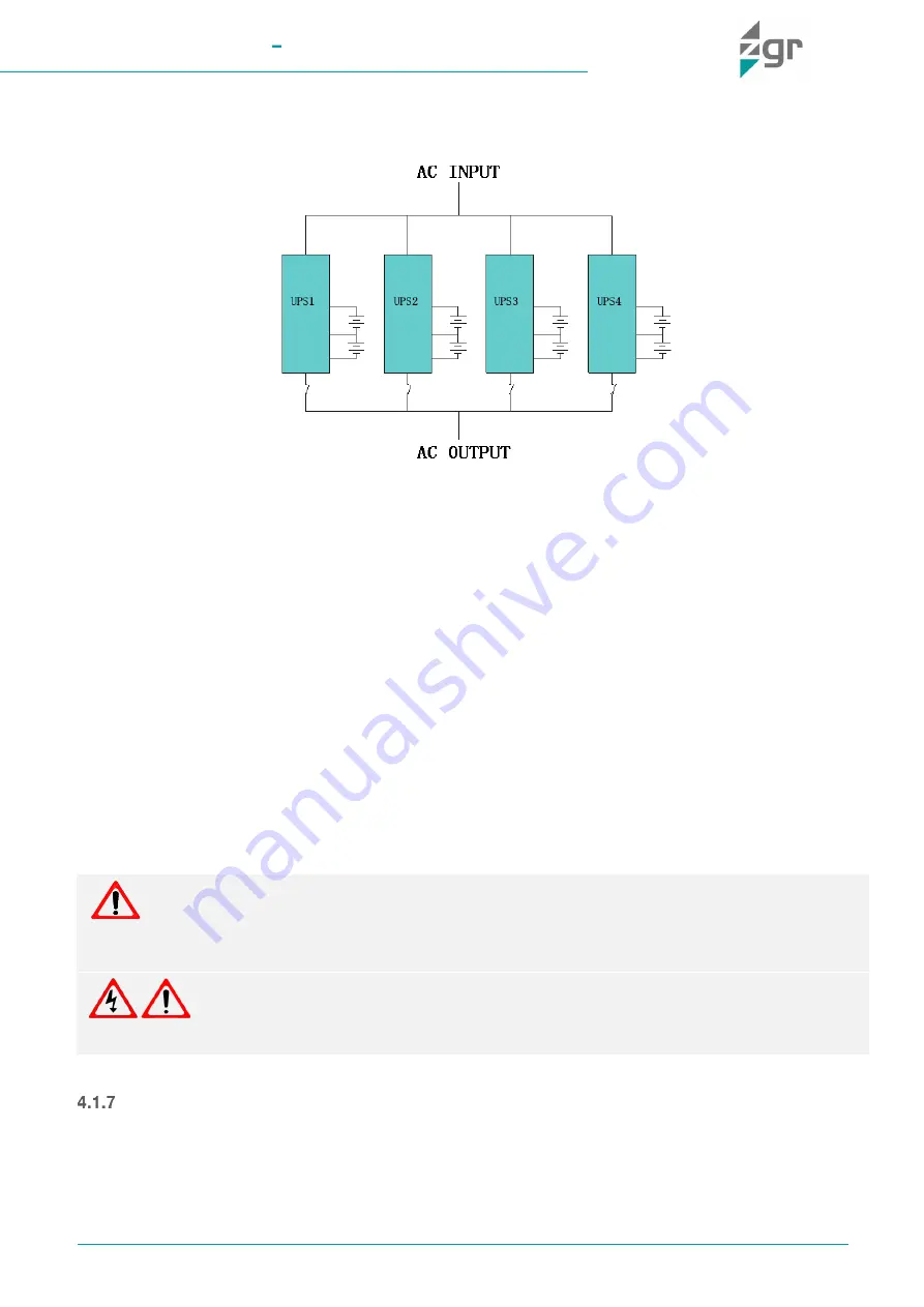
Connect the UPS with parallel cables.
Fig. 4-1 Parallel connection
2)
Connect all the outputs of the parallel UPS using individual breakers to one patch board before connect to
the loads. See the Fig. 4-1 as follows.
3)
Adjust each UPS settings through LCD. See the Manual Chapter 4.3.1; 4.3.10; 4.3.11; 4.3.12.
A.
Each UPS must be configured individually.
B.
Set relevant parameters as below
:
①
Working mode: set as Parallel operation;
②
Parallel ID: set different UPS ID one by one;
③
Parallel amount: set the amount of UPS in parallel.
C.
Power OFF UPS and continue with next unit.
4)
Now close output breakers to make work in parallel mode
5)
Once all UPS was configured, make sure all connections and wire sequence are correct, and then can be
powered ON at same time or one by one.
Parallel cable installation
Shielded and double insulated control cables available must be interconnected in a ring configuration between
UPS modules. The parallel control board is included on each UPS module. The ring configuration ensures high
reliability of the control.
WARNING
When the UPS in parallel, the input can be the same or different, but the output should be paralleled to one
patch board.
WARNING!
Make sure the N, L lines are correct, and ground is well connected.


