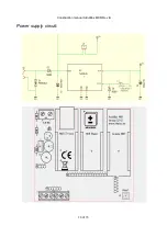
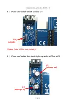
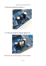
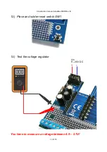
background image

Construction manual ArduiBox MKR Rev B

Parts Basic Version:


1x

2pole terminal block

2x

3pole terminal block

4x

14pole centipede header 

2x

14pole male header 

1x

Schottky diode 

SB260

(D2)

2x

self-tapping screws

4 of 15

cathode

Summary of Contents for 103495

Page 1: ...Construction manual ArduiBox MKR Rev B ArduiBox MKR Rev B construction manual Rev Date Description A 2018 05 15 First Release B 2020 12 17 Changed tor new ArduiBox MKR 2 0 1 of 15 ...

Page 2: ...Construction manual ArduiBox MKR Rev B Tools a regulated soldering iron 25 40W with small tip a wet sponge to clean the tip thin solder wire Side cutting pliers Needle nose pliers 2 of 15 ...

Page 3: ...Construction manual ArduiBox MKR Rev B Medium cross slot screwdriver 3 of 15 ...

Page 4: ...on manual ArduiBox MKR Rev B Parts Basic Version 1x 2pole terminal block 2x 3pole terminal block 4x 14pole centipede header 2x 14pole male header 1x Schottky diode SB260 D2 2x self tapping screws 4 of 15 cathode ...

Page 5: ...KR Rev B 1 Place and solder the centipede headers Please assemble the 4 female centipede headers as in the picture below 2 Place and Solder the male headers Please assemble the 2 straight male headers as in the picture below 5 of 15 ...

Page 6: ...al ArduiBox MKR Rev B 3 Place and solder the diode D2 4 Place and solder the terminal K9 We ve to put the block into the proto plate Make sure you place them so that the open ends are facing out as shown 6 of 15 cathode ...

Page 7: ...ind the terminal blocks they re grey or blue and come in 3 pin shape We ll need to slide two 3 pin blocks together 6 Place and solder 3pole terminal blocks We ve to put the blocks into the proto plate Make sure you place them so that the open ends are facing out as shown 7 of 15 ...

Page 8: ...or of the standard kit If you want to use the USB socket of the Arduino MKR for powering this step is unnecessary also Please note The supply voltage connected to K9 has to be 5V DC in this case Perform the next steps only if you have the standard kit includes the parts of the voltage regulator Otherwise continue with step 14 8 of 15 Solder this Jumper ...

Page 9: ... Standard Version 1x inductor 100uH 2 0A L1 1x Schottky diode SB260 D3 1x overvoltage limiting diode P6KE36CA D1 1x voltage regulator TL2576 5 IC1 1x electrolytic capacitor 100uF 63V C1 1x electrolytic capacitor 1000uF 16V C2 1x Reset Button S1 9 of 15 cathode ...

Page 10: ...Construction manual ArduiBox MKR Rev B Power supply circuit 10 of 15 ...

Page 11: ...truction manual ArduiBox MKR Rev B 8 Place and solder Diode D3 and D1 Please Note D1 has no polarity 9 Place and solder the electrolytic capacitors C1 and C2 11 of 15 D3 cathode C1 minus pole C2 minus pole ...

Page 12: ...Construction manual ArduiBox MKR Rev B 10 Place and solder the inductor L1 11 Place and solder the voltage regulator IC1 Note Please take care that the jumper J3 is not be bridged 12 of 15 ...

Page 13: ...Construction manual ArduiBox MKR Rev B 12 Place and solder reset switch SW1 13 Test the voltage regulator You have to measure a voltage between 4 9 5 1V 13 of 15 Vin 9 35V DC ...

Page 14: ...Construction manual ArduiBox MKR Rev B 14 Mount the pcb into the bottom shell 15 Fix the pcb in the lower shell with the screws 14 of 15 Recess in the lower shell ...

Page 15: ...Construction manual ArduiBox MKR Rev B 16 Mount the Arduino MKR shields It s time to mount the Arduino MKR board and optional shields 17 Mount the top shell Finish 15 of 15 ...

Reviews: