SR981S/SR982S operation manual of solar pump station
Page 51 of 85
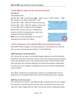
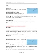
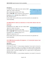
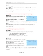
8.4.5 REC Recooling temperature of tank
Description:
If storage temperature rises up to its maximum temperature, and at the same time,
collector temperature is 5
o
C lower than storage temperature, then solar pump can be
triggered, through this reversed circulation, tank temperature is reduced by heat loss
occurs in collector, solar pump keeps in working until tank temperature drops below its
maximum temperature.
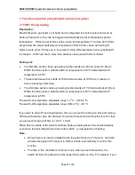
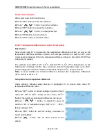
Setup steps:
To ac
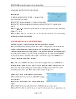
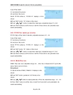
cess main menu TEMP, then select submenu REC, “REC OFF” shows on the screen,
default set is off.
►Press “SET” button, parameter “OFF” blinks on the
screen
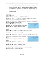
►Repress “SET” button to activate or deactivate this
function; after function activated, factory set is “REC ON”
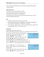
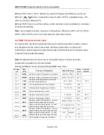
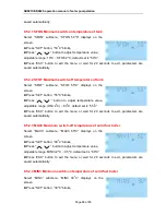
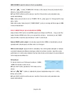
► Press “ESC” button to exit the menu or wait for 20 seconds to exit, parameters are
saved automatically.
REC sign blinks on the screen; it indicates that this function is activated.
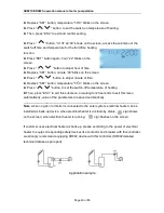
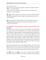
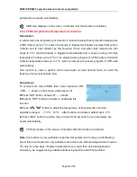
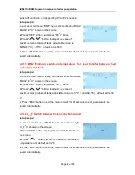
8.4.6 SMX1 Maximum temperature of tank 1
Description:
When the DT between collector T1 and tank T2 meets the switch-on DT of circulation, solar
pump is triggered, but in order to avoid the high temperature inside tank, controller will
check whether the temperature (T3) of the top part of tank is higher than the maximum
temperature of tank, when T3 is higher than the preset maximum tank temperature SMX,
solar pump is ceased even at the case that DT caters condition. When tank temperature
drops and is 2
o
C below the SMX temperature, solar pump restarts when DT meets the
condition.
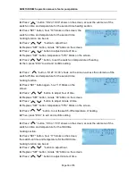
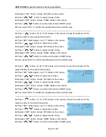
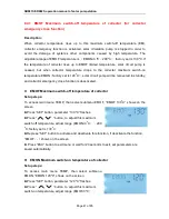
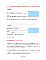
Setup steps:
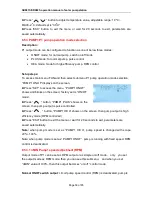
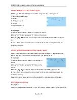
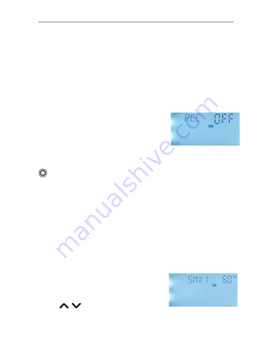
To access main menu TEMP, then select submenu SMX1,
“SMX1 60
o
C” shows on the screen.
►Press “SET” button, parameter “60
o
C” blinks
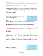
►Press
“
” button to adjust the value of


