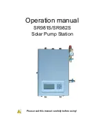
SR981S/SR982S operation manual of solar pump station
Page 7 of 85
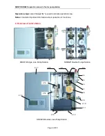
2.1
Collector flow pipe connections, male thread G1/2( to collector)
2.2
Sensor on the tank output pipe, NTC10K, B=3950
2.3
Safety valve, release pressure 6 bar
2.4
Pressure gauge, measuring range: 0~10bar system pressure
2.5
Expansion connection, male thread G1/2
2.6
Filling valve connection, male thread G1/2
2.7
One
– way stop valve
2.8
Circulation pump ( for solar liquid)
2.9
Draining valve connection, male thread G1/2
2.10
Electrical flow meter
2.11
Connection terminal box of built-in controller
2.12
Tank output pipe connection ( from tank), male thread G1/2
2.13
Tank input pipe connection(to tank), male thread G1/2 (not on SR981S single pipe
pump station)
2.14
Manual and automatic combined air separator (not on SR981S single pipe pump
station)
2.15
Sensor on the collector return pipe ( high temperature) NTC10K, B=3950 (not on
SR981S single pipe pump station)
2.16
Collector return pipe connection, male thread G1/2 ( from collector) (not on SR981S
single pipe pump station)
2.17
Front cover of pump station
2.18
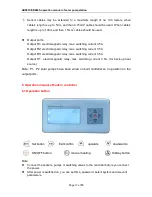
Display and control panel of built-in controller
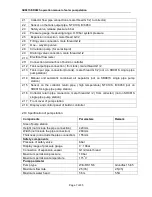
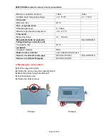
2.19 Specification of pump station
Components
Parameters
Remark
Size of pump station
Height (not include the pipe connection)
420mm
Width (not include the pipe connection)
280mm
Thickness (not include the pipe connection)
155mm
Safety components
Pressure of safety valve
6bar
Display range of pressure gauge
0
~
10bar
Connection of expansion vessel
G1/2,male thread
Maximum permission pressure
10 bar
Maximum permission temperature
115
o
C
Pump parameter
Pump type
Wilo RS15/6
Grundfos 15-65
Maximum flow rate
2.5(t/h)
2.5(t/h)
Maximum water head
5.5m
5.5m

