background image

INSTALLATION AND OPERATING INSTRUCTIONS:

2-jaw parallel gripper, electric, GEP2000 series

INSTALLATION AND OPERATING INSTRUCTIONS:

2-jaw parallel gripper, electric, GEP2000 series

7

Zimmer GmbH 

 Im Salmenkopf 5 

 77866 Rheinau, Germany 


+49 7844 9138 0 

• 

 +49 7844 9138 80 

 www.zimmer-group.com

EN / 2021-07-08

DDOC01113-01 / a

7.2  Installing the power supply "GEP20xxIO-12-B-01"

7.2.1  Installing the wiring
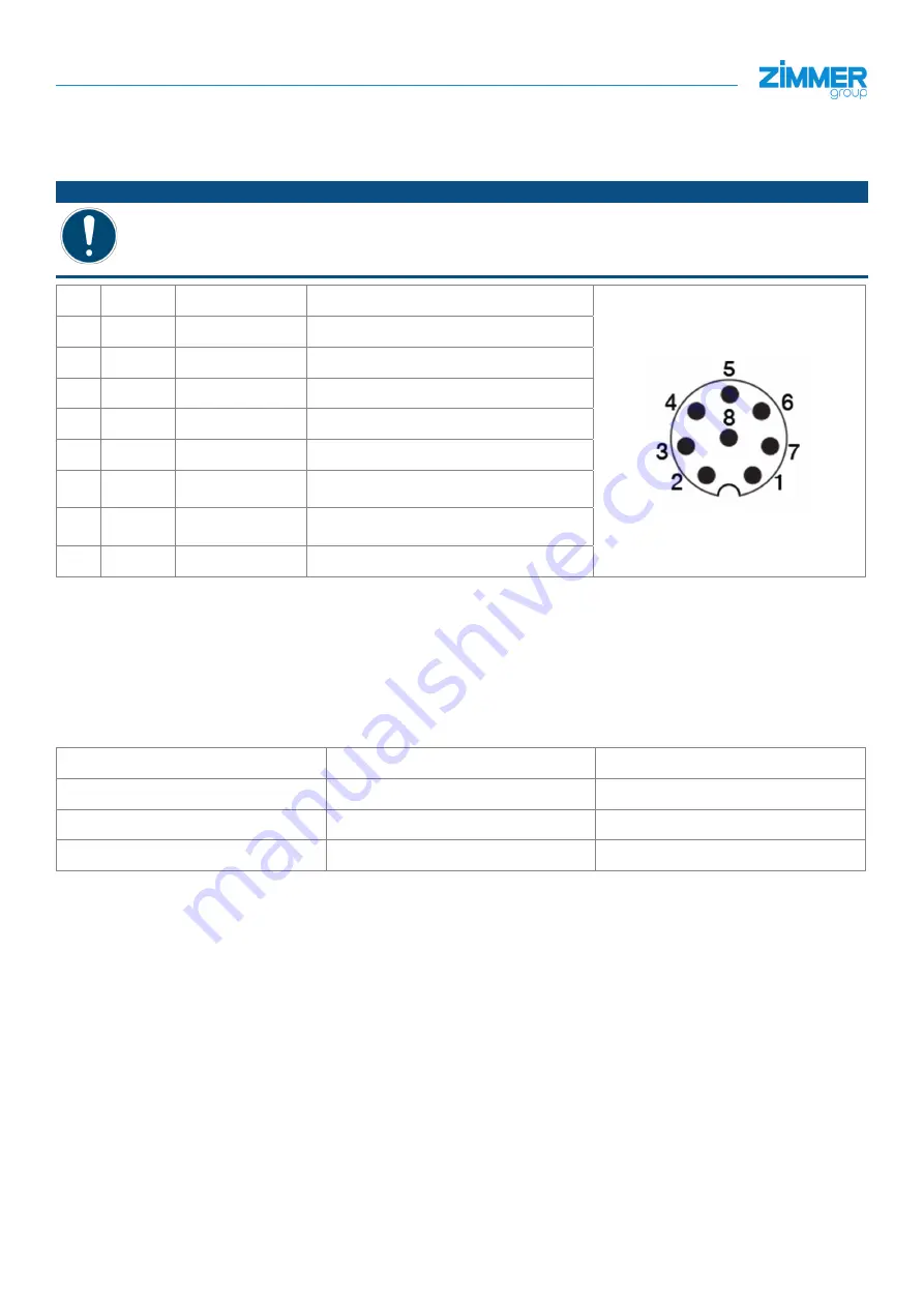
NOTICE

Non-compliance may result in material damage.

A correct pin assignment must be ensured.


Ö

The product may be ruined and malfunction.

PIN Color

Function

Explanation

1

White

Analog output

0 to 10 V output

2

-

-

-

3

-

-

-

4

-

-

-

5

Gray

+ 24 V DC

+ 24 V DC supply voltage

6

Pink

Move command

Input, control input for inward move 

command

7

Blue

Move command

Input, control input for outward move 

command

8

Red

GND

0 V DC supply voltage

The following steps must be carried out for commissioning or installing the "GEP20xxIO-12-B-01" product:


Connect the product to the voltage supply.


Secure the voltage supply.


Ö

A voltage supply between PIN 5 and PIN 8 is necessary for operation.


Ö

A jaw movement is triggered by a voltage level between PIN 7 or PIN 6.

Control logic:

Movement

PIN 7 (open)

PIN 6 (close)

Product in rest mode

0

0

Open the product

1

0

Close the product

0

1

A movement in the desired direction occurs when the corresponding signal is at a high level. After a high level is detected, 

the gripper movement occurs until the gripping process ends.
It is important to ensure that the corresponding signal is reset after successful movement has taken place.
This must happen before a signal is carried out in the opposite direction.

Between withdrawing the signal and the next command, a pause time of 10 ms must be adhered to.

Summary of Contents for GEP2000 Series

Page 1: ...oup de INSTALLATION AND OPERATING INSTRUCTIONS GEP2000 series 2 jaw parallel gripper Robot specific electric GEP2006IO 12 B 01 GEP2010IO 12 B 01 GEP2013IO 12 B 01 GEP2016IO 12 B 01 DDOC01113 01 THE KNOW HOW FACTORY ...

Page 2: ... tolerance window for the TeachPosition BasePosition and WorkPosition The value of the parameter acts in both directions BasePosition The BasePosition is the outer JawPosition Depending on the gripper profile this can also be a work position ShiftPosition The ShiftPosition is a switching position between pre positioning and gripper movement StatusWord In its bits the StatusWord returns the most im...

Page 3: ...113 01 a Content 1 Supporting documents 4 1 1 Notices and graphics in the installation and operating instructions 4 2 Safety notices 5 3 Proper use 5 4 Personnel qualification 5 5 Product description 5 6 Function 6 7 Installation 6 7 1 Installing the power supply 6 7 2 Installing the power supply GEP20xxIO 12 B 01 7 7 2 1 Installing the wiring 7 8 More information 8 9 Declaration of Incorporation ...

Page 4: ... of an imminent danger to the life and health of people Ignoring these notices can lead to serious injury or even death You absolutely must comply with the described measures for avoiding these dangers Ö The warning symbols are assigned according to the type of danger WARNING This notice warns of a situation that is potentially hazardous to personal health Ignoring these notices can cause serious ...

Page 5: ...hen it is in a technical condition that corresponds to the guaranteed parameters and operating conditions Ö Zimmer GmbH shall accept no liability for any damage caused by improper use The operator bears sole responsibility The product is designed exclusively for electric operation using a 24 V DC power supply The product must always be mounted on materials that dissipate heat The product is to be ...

Page 6: ...nstallation INFORMATION Information about the installation can be found in the standardized installation and operating instructions DDOC01113 or on our website Zimmer Customer Service is available to provide you with assistance if you have any further questions 7 1 Installing the power supply INFORMATION The cables that are used by Zimmer GmbH feature a minimum bending radius of 10 x the outer dia...

Page 7: ...supply voltage The following steps must be carried out for commissioning or installing the GEP20xxIO 12 B 01 product Connect the product to the voltage supply Secure the voltage supply Ö A voltage supply between PIN 5 and PIN 8 is necessary for operation Ö A jaw movement is triggered by a voltage level between PIN 7 or PIN 6 Control logic Movement PIN 7 open PIN 6 close Product in rest mode 0 0 Op...

Page 8: ...ized installation and operating instructions DDOC01113 Commissioning Operation Error diagnosis Maintenance Accessories scope of delivery Transportation storage disposal Decommissioning disposal RoHS Declaration REACH Declaration 9 Declaration of Incorporation Conformity INFORMATION The Declaration of Incorporation and Conformity can be found in the standardized installation and operating instructi...

Reviews: