background image

INSTALLATION AND OPERATING INSTRUCTIONS: 

GPH8000

INSTALLATION AND OPERATING INSTRUCTIONS: 

GPH8000

EN / 2021-10-19

EN / 2021-10-19

6  Functional description

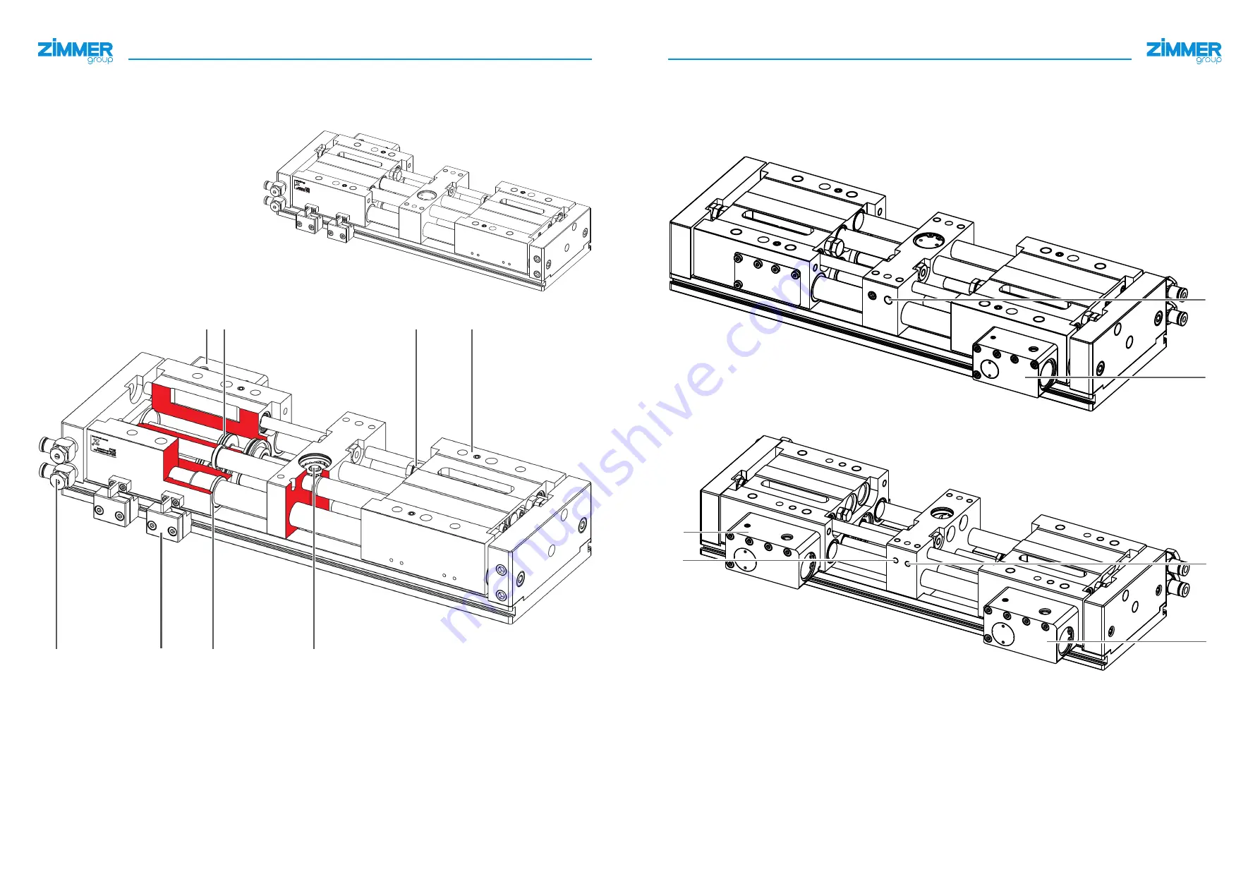
The product has two pneumatic pistons that are vented on both sides. Alternating ventilation sets the gripper jaws in 

motion. The power supply can be made one-way or two-way. 

1

Clamping element

2

Drive

3

Stroke limitation

4

Gripper jaw

5

Power supply

6

Terminal block

7

Round guide

8

Synchronization

2

1

3

4

5

6

7

8

Clamping elements are used to secure the gripper jaws. This securing element is transfered to both gripper jaws by the 

synchronization in the CL-00 variant. In the CL-30 variant, two clamping elements are installed. These can be actuated 

independently of each other. There are no clamping elements installed in the N-00 variant. The clamping elements are 

pre-tensioned by a spring in order to secure the jaw position in case of a drop in pressure. Applying pressure releases the 

clamping element.

CL-00 variant

9

bl

CL-30 variant

bn

9

bm

bl

9

Open clamping element 1

bm

Clamping element 2 (CL-30 variant)

bl

Clamping element 1

bn

Open clamping element 2 (CL-30 

variant)

Zimmer GmbH • Im Salmenkopf 5 • 

 77866 Rheinau, Germany • 

 +49 7844 9138 0 • www.zimmer-group.com

Zimmer GmbH • Im Salmenkopf 5 • 

 77866 Rheinau, Germany • 

 +49 7844 9138 0 • www.zimmer-group.com

DDOC00289 / b

DDOC00289 / b

6

7

Summary of Contents for GPH8000 Series

Page 1: ...INSTALLATION AND OPERATING INSTRUCTIONS 2 jaw parallel grippers with long stroke GPH8000 series DDOC00289 THE KNOW HOW FACTORY www zimmer group com ...

Page 2: ...these dangers Ö The warning symbols are assigned according to the type of danger CAUTION This notice warns of a situation that is potentially hazardous for people or that may result in material or environ mental damage Ignoring these notices may result in slight temporary injuries or damage to the product or to the environment You absolutely must comply with the described measures for avoiding the...

Page 3: ...st modify maintain or repair the product Whenever work is carried out on the product make sure that the product cannot be actuated by mistake Perform maintenance tasks retrofitting or attachment work outside of the machine s danger zone when possible Do not reach into the operational range of the product Observe the specified maintenance intervals and compressed air quality specifications When usi...

Page 4: ... gripper jaws by the synchronization in the CL 00 variant In the CL 30 variant two clamping elements are installed These can be actuated independently of each other There are no clamping elements installed in the N 00 variant The clamping elements are pre tensioned by a spring in order to secure the jaw position in case of a drop in pressure Applying pressure releases the clamping element CL 00 va...

Page 5: ...ion WARNING Risk of injury in case of non compliance Risk of injury in case of uncontrolled movements of the machine or system into which the product is to be installed The opening pressure for the product and the installed clamp is at least 4 bar Switch off the power supply of the machine before all work Secure the power supply against being switched on unintentionally Check the machine for any r...

Page 6: ... the product Only use the product with the supplied flow control valves NOTICE Close off unused pneumatic connections using suitable dummy plugs The authorized pneumatic connections that are available can be found in the accessories list on our website The necessary ordering information can also be found there Use compressed air in accordance with DIN ISO 8573 1 4 4 4 INFORMATION You can find info...

Page 7: ...sion Move to the end stop Set the stroke adjustment screw on the second gripper jaw Secure the stroke adjustment screws with a suitable threadlocker and lock nut 10 3 2 Asynchronous Set each jaw stroke independently of each other using the stroke adjustment screws Secure the stroke adjustment screws with a suitable threadlocker and lock nut cm cm cm cm cm Stroke adjustment screw 10 3 3 Mounting th...

Page 8: ...ting malfunctions or damage 12 Decommissioning disposal INFORMATION When the product reaches the end of its operational phase it can be completely disassembled and disposed of Disconnect the product completely from the power supply Dispose of the components properly according to the material groups Comply with the locally applicable environmental and disposal regulations RoHS declaration In terms ...

Page 9: ... principles for design Risk assessment and risk reduction A full list of applied standards can be obtained from the manufacturer We also declare that the specific technical documents were produced in accordance with Annex VII Part B of this Directive We undertake to provide the market supervisory bodies with electronic versions of special documents for the incomplete machine through our documentat...

Reviews: