background image

INSTALLATION AND OPERATING INSTRUCTIONS:


Motor spindle, HF125-002 series 

Zimmer GmbH 

 Im Salmenkopf 5 

 77866 Rheinau, Germany 


+49 7844 9138 0 

• 

 +49 7844 9138 80 

 www.zimmer-group.com

16

EN / 2020-11-25

DDOC00743 / -

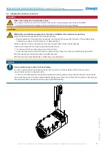
9.4  Installing the power supply

CAUTION:

Malfunction due to improper power supply installation

Installing the power supply correctly ensures that the product will function properly.


Ö

Always install flexible power supply lines.

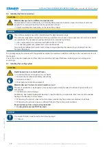
NOTICE:

Function of the product is ensured

The function of the product is ensured if:

• 

The power supply lines have adequate dimensions

• 

The power supply lines are used that are as short as possible and shielded throughout their entire length

If the power supply lines do not have adequate dimensions, the product might have an insufficient supply.


Ö

Fault or damage to the product.

INFORMATION:

The bending radius of the power supply lines must not fall below the minimum value!
Cables that are hanging freely must be affixed!


Ö

Excessive movement stress or crushing must be avoided.

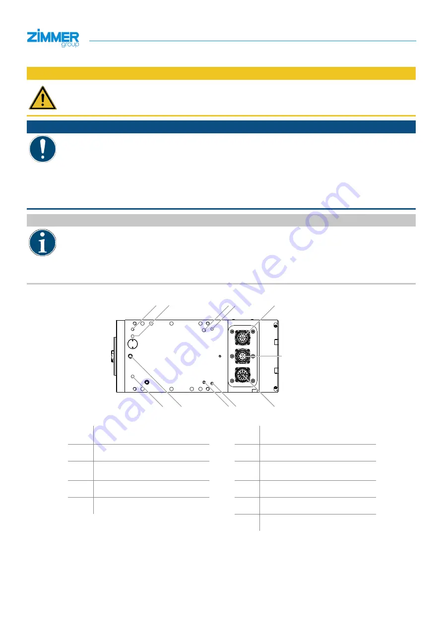
Refer to the technical datasheet for the wiring diagrams, plug coding and fluid connections.

E A

XG2

XD1

KR

F

SPL

H2

H1 H3

XG3 (optional)

H1

Controllable connection

XD1

Power connection and signal 

connection

H2

Controllable connection

XG2 Signal connection

H3

Controllable connection

XG3 Position sensor and speed sensor 

(optional)

SPL

Purging air

F

Cooling system, recirculation

KR

Cone cleaning

E

Cooling system, feed

A

Release the tool

Summary of Contents for HF125-002

Page 1: ...www zimmer group de INSTALLATION AND OPERATING INSTRUCTIONS HF125 002 Motor spindle DDOC00743 THE KNOW HOW FACTORY ...

Page 2: ...n it in a state of constant readiness and efficiency operating personnel must be thoroughly trained by our experts These installation and operating instructions are a constituent part of the operating instructions of the machine in which this incomplete machine is installed and shall be kept available for operating personnel to use at all times in accordance with the Machinery Directive For this r...

Page 3: ...N 2020 11 25 DDOC00743 Glossary Abbreviation Explanation HSK Hollow taper shank MSDS Material safety datasheets PTC Positive temperature coefficient thermistor SBT Silicon based thermistor MQL Minimum quantity lubrication MQCL Minimum quantity cooling lubrication Handling instructions Ö Ö Consequences or additional information of an instruction Bulleted list 1 Bulleted list 2 ...

Page 4: ...oder 13 9 Installation 14 9 1 Safety notes 14 9 2 General installation information 15 9 3 Installing the product 15 9 4 Installing the power supply 16 9 5 Installing electrical connections 17 9 6 Installing the fluid connections 18 9 7 Installing the cooling system 18 9 7 1 Cooling duct connections 20 9 7 2 Requirements for the mounting surface 20 9 7 3 Cooling unit 20 9 7 4 Requirements for the c...

Page 5: ...12 1 Safety note 30 12 2 Cleaning agents 31 12 3 Definitions of maintenance work 31 12 3 1 Visual inspection of the product 31 12 3 2 Inspection of the product 31 12 3 3 Maintenance of the product 31 12 3 4 Overhauling of the product 31 12 4 Maintenance plan 32 13 Disassembly for decommissioning 33 14 Decommissioning and disposal 33 15 Cleaning preservation 33 16 Storage 34 17 Recommissioning 34 1...

Page 6: ...alth of people Ignoring these notices can result in serious injury or death You absolutely must comply with the described measures for avoiding these dangers Ö Ö The warning symbols are assigned according to the type of danger WARNING This notice warns of a situation that is potentially hazardous to personal health Ignoring these notices can result in serious injury or damage to health You absolut...

Page 7: ...ing devices or attachment equipment may damage the product Ö Ö Do not use any chains or steel cables Ö Ö Use only tested lifting belts with sufficient load capacity 3 2 Transportation data CAUTION Improper transportation Improper handling of the transportation box will cause transport damage to the product Ö Ö Do not tilt the transportation box Ö Ö Avoid powerful vibrations and impacts NOTICE Tran...

Page 8: ...uated by mistake Modifications to the product such as adding drilled holes or threads may be made only with prior approval from Zimmer GmbH The specified maintenance intervals are to be observed also refer to the Maintenance section When the product is used under extreme conditions the maintenance interval must be adapted Use of the product under extreme conditions such as aggressive liquids and a...

Page 9: ... the following production methods Machining with geometrically defined cuts dry machining DIN 8589 0 for non abrasive materials Drilling counterboring reaming DIN 8589 2 Milling DIN 8589 3 Grinding DIN 8589 0 The product is used to hold and drive cutting tools Permitted materials Wood Plastics Light metals non ferrous metals or comparable materials Any other or more extensive use is improper Zimme...

Page 10: ...f a frequency converter An inductive analog sensor is installed for speed sensor monitoring and standstill monitoring The heat created by the motor must be discharged by a suitable cooling system The product features corresponding internal cooling ducts The loosening unit is designed for automatic tool exchanges A high resolution rotary encoder can be installed as an option for speed control stand...

Page 11: ...ING INSTRUCTIONS Motor spindle HF125 002 series 11 Zimmer GmbH Im Salmenkopf 5 77866 Rheinau Germany 49 7844 9138 0 49 7844 9138 80 www zimmer group com EN 2020 11 25 DDOC00743 1 2 3 4 5 6 7 8 9 bl bl bl bm bp br bo bq bo bn ...

Page 12: ...tool holder is detected by a sensor and is transmitted to the machine control system as digital signals Refer to the specifications for the technical design of the sensors Three clamping states are available Clamped without tool Clamped with tool Tool unclamped The circuit diagram of the clamping states is provided on the technical datasheet 8 3 Standstill monitoring DANGER Risk of fatal injury an...

Page 13: ...y encoder and your control system Ö Ö It must be made impossible for personnel to be able to stand inside the safety device or to enter it while the product is rotating Risk of fatal injury and damage to the product when operating without signals from the speed sensor The speed signal must be generated from the installed sine cosine encoder with two independent speed signals Otherwise there is a r...

Page 14: ...t must be checked for damage in transit after each time it is transported It is absolutely necessary to avoid any vibrations or impact Potential consequences of damage in transit include serious personal injury or significant material damage Risk of injury in case of unexpected movement of the machine or system into which the product is to be installed Switch off the power supply to the machine be...

Page 15: ... sufficiently rigid INFORMATION When installing the product you must ensure that there is sufficient clearance space around the product Observe the following measures Ensure a sufficient amount of air circulation or cooling Ö Ö Ensure sufficient dimensions for the machining area room size enclosure Ö Ö Provide a sufficient fresh air supply Do not install any additional heat sources at the product ...

Page 16: ...ible and shielded throughout their entire length If the power supply lines do not have adequate dimensions the product might have an insufficient supply Ö Ö Fault or damage to the product INFORMATION The bending radius of the power supply lines must not fall below the minimum value Cables that are hanging freely must be affixed Ö Ö Excessive movement stress or crushing must be avoided Refer to the...

Page 17: ...g contacts are properly oriented and are not damaged bent Faulty connection of the grounding wire will cause a health hazard and material damage Observe the measures for protection against electrical shock Ö Ö Connect product s ground conductor and the machine Ö Ö Personnel may work near the electrical components only if they are properly and sufficiently grounded Personnel are grounded by means o...

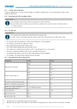
Page 18: ...nical Datasheet To optimally supply the product with the operational media the media are transferred directly via the rear side interface of the product Check the connection pressures and flow rates in accordance with specifications and design your mounting piece accordingly 9 7 Installing the cooling system CAUTION Health hazard due to coolant antifreeze Ö Ö Coolant antifreeze is dangerous to you...

Page 19: ... use Unsuitable coolant can lead to thermally insulating deposits on parts that transfer heat Zimmer GmbH accepts no liability for any resulting malfunctions or damage Zimmer GmbH recommends the use of Cool Core Ready from Motorex SK3301 960 from Rittal or a comparable coolant All trials and test runs were carried out with one of the coolants specified above Incorrect pH value of the coolant The c...

Page 20: ...cooling unit with adequate cooling capability Ö Ö The cooling unit must have temperature control Ö Ö Recommended flow temperature of the product 25 C at an ambient temperature of a maximum of 35 C If the difference in temperature is greater than 10 C condensate can form in the product Too great a temperature difference can result in damage to the product At an ambient temperature above 35 C the fl...

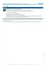
Page 21: ...faulty operation of the KR connection Ö Ö Observe the circuit diagram Ö Ö Observe the tool exchange diagram Material damage from actuation of the KR connection By actuating the KR connection without actuating the A connection at the same time the compressed air can expand in the product in an uncontrolled manner causing damage The product has an integrated cone cleaning system KR connection This c...

Page 22: ...sioning Inadequate safety conditions result in a health hazard and material damage Removing safety devices during the commissioning of the machine can cause serious injury Ö Ö First bring the machine properly out of operation Immediately after completion of commissioning Ö Ö Return the safety unit to its original or correct condition and inspect it CAUTION Material damage caused by the overheating...

Page 23: ...efore each instance of commissioning or operation of the product The product must never rotate or be operated without having carried out the commissioning test described here Check the tightening torques product mounting piece Check the power supply lines and connections Check the operating parameters Check the standstill monitoring Check the function clamping force and nominal dimensions of the s...

Page 24: ...te the loosening unit using the machine control system to release the tool Remove the tool or unit from the product in the axial direction Clean the product using a clean soft rag Plane face of the tool holder Gap between the quick change tool adapter and the surface of the taper To extend the clamping set actuate the loosening unit by using the machine control system Ö Ö The clamping system is un...
Page 25: ...analog sensor and switching states DANGER Risk of fatal injury as a result of prohibited tool interface clamping states Ö Ö The product may only be operated if the state Clamped with tool is met Ö Ö Otherwise a loss ejection of the tool during operation rotation cannot be ruled out Ö Ö Injury to personnel or material damage may result The analog sensor installed in the product monitors the clampin...

Page 26: ...PTC130 thermistor CAUTION Material damage from inappropriate thermistor settings Operating the product with a PTC130 thermistor value above 4000 Ω will cause damage to or destruction of the product Ö Ö Never exceed the PTC130 thermistor value of 4000 Ω Ö Ö If the PTC130 thermistor reaches this value the product must be stopped immediately The characteristic curve of the PTC130 thermistor shows a s...

Page 27: ...ly while product is at a standstill Clamp the tools or units firmly and securely Never exceed the tool manufacturer s maximum specified speed Only use tools and tool holders that comply with the following properties Tool interface with a hollow taper shank in accordance with DIN 69893 6 Balance quality G2 5 DIN ISO 1940 A balance quality of G2 5 to G6 3 DIN ISO 1940 will shorten the life cycle A b...

Page 28: ...f the product In extreme cases damage to the product cannot be ruled out Ö Ö Observe the warm up cycle In order to ensure the product achieves the longest possible life cycle a warm up cycle must be carried out after any standstill period longer than four hours Operate the product as follows Ö Ö Angular acceleration α 200 rad sec 1 warm up cycle At ambient temperatures above 10 C 2 warm up cycle A...

Page 29: ...ximum tool weight 6 kg Maximum tool length including holder 280 mm Balancing quality Tool fixture with tool dynamically balanced according to ISO 1940 G2 5 Will shorten the life cycle G2 5 to G6 3 A balance quality above G6 3 according to DIN ISO 1940 will shorten the life cycle signifi cantly and must not be used Above G6 3 Direction of rotation left right Maximum concentricity error 0 02 mm 11 4...

Page 30: ...hed back on again Risk of injury caused by falling loads Improper handling of hanging loads can cause serious injuries Note the following points Ö Ö Secure hanging loads by using the provided attachment equipment and set workpieces down before working in the danger zone Ö Ö Wear appropriate personal protective equipment Ö Ö Always keep an adequate safety distance from hanging loads Ö Ö Never walk ...

Page 31: ...the product The visual inspection merely includes visually inspecting component parts and their function If any irregularities or damage are identified during the visual inspection a more detailed check of the component parts must be carried out 12 3 2 Inspection of the product The inspection includes the check of the product When performing the inspection the actual status of the product must be ...

Page 32: ... actual dimension pH value of the coolant optional Cooling circuit optional Coolant optional Air cooling filter Cooling ducts air ducts in the spindle housing Power supply lines in their entirety Electrical system Grease distribution during recommis sioning Inspection Daily Weekly Monthly Annually Visual inspection Daily Weekly Monthly Annually Cleaning Daily Weekly Monthly Annually As required Ma...

Page 33: ...aches the end of its operational phase it can be completely disassembled and disposed of Completely disconnect the product from the power supply The product can be disassembled and properly disposed of according to material groups When disposing it observe the locally applicable environmental regulations and codes and regulations for disposal If it is not possible to properly disassemble and dispo...

Page 34: ...operly Ö Ö The operator must provide for a sufficient storage area Ö Ö The original packaging must not be stacked The product must be stored in its original packaging or in a similar packaging variant in a closed and dry room that is protected from the weather The following storage and transportation conditions must be complied with Storage conditions Units Values Minimum temperature C 10 Maximum ...

Page 35: ...in Air pressure too low Check air pressure Increase Release tool air pressure Water in the cleaning air Install water separator Temperature sensor in the product has tripped Cooling system is not switched on Switch on cooling system Cooling system is not functional Check cooling system Product is overloaded Reduce load Collet chuck status is invalid Product tool holder or holder on the unit is dir...

Page 36: ... series Zimmer GmbH Im Salmenkopf 5 77866 Rheinau Germany 49 7844 9138 0 49 7844 9138 80 www zimmer group com 36 EN 2020 11 25 DDOC00743 20 Appendix Spare parts list Technical datasheet HF125 002 xxx Motor datasheet Third party company instructions HSK clamping set ...

Page 37: ...h See manufacturer s address Rheinau Germany 2020 09 15 Martin Zimmer First name last name Address Place and date of issuance Legally binding signature Managing Partner 22 REACH declaration in terms of the EU Regulation 1907 2006 Name and address of the manufacturer Zimmer GmbH Im Salmenkopf 5 77866 Rheinau Germany 49 7844 9138 0 49 7844 9138 80 www zimmer group com REACH stands for Registration E...

Page 38: ...ery Functional safety of electrical electronic and programmable electronic control systems DIN EN ISO 10218 2 Industrial robots robot systems and integration DIN EN IOS 13849 Safety of machinery Safety related parts of control systems ISO TS 15066 Human Robot Collaboration A full list of applied standards can be obtained from the manufacturer We also declare that the specific technical documents w...

Page 39: ...e 2014 30 EU in its design and the version we put on the market The following harmonized standards have been used DIN EN ISO 12100 2011 03 Safety of machinery General principles for design Risk assessment and risk reduction DIN EN 61000 6 3 EMC Generic standard Emission standard for residential commercial and light industrial environments DIN EN 61000 6 2 EMC Generic standard Immunity for industri...

Page 40: ...INSTALLATION AND OPERATING INSTRUCTIONS Motor spindle HF125 002 series Zimmer GmbH Im Salmenkopf 5 77866 Rheinau Germany 49 7844 9138 0 49 7844 9138 80 www zimmer group com 40 EN 2020 11 25 DDOC00743 ...

Reviews: