Page 8 INSTRUCTION MANUAL CENTRAL COMMAND STATION MX10
Higher current on the tracks, by...
interconnecting the MX10’s track outputs,
or
a number of MX10s in a Master-Booster arrangement
SW July 2018 - SW 01.24 and higher
In case the “normal” track output of the MX10 (“S1” with 12 A traction current) is not enough to supply the
layout, frankly, there are two possibilities: interconnecting the two trac
k outputs (“S1” and “S2” with con-
figuring “SYNC” in “MX10 CONFIG”) to a power circuit of about 20 A, or the usage of booster devices
(specially configured MX10).
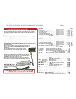
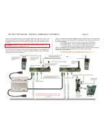
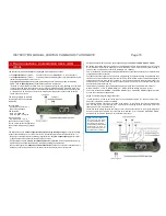
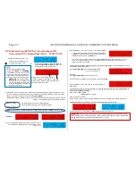
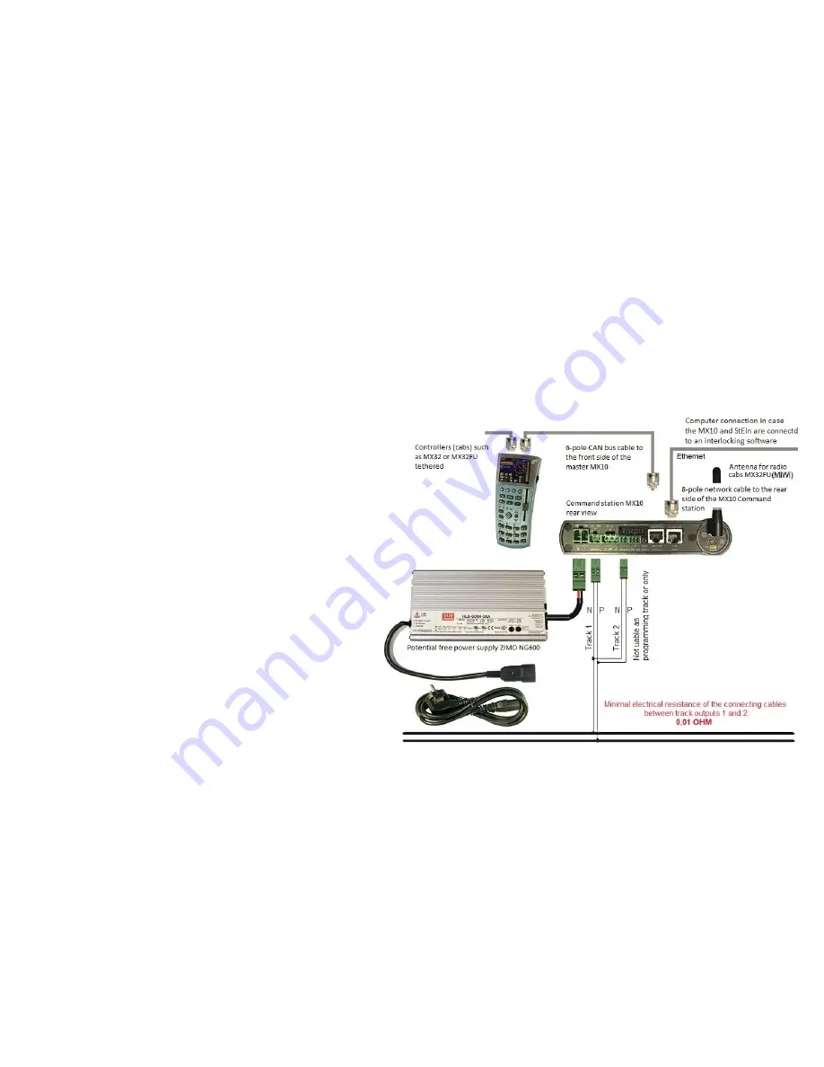
Interconnecting the MX10’s outputs
(picture on the right):
The outputs “S1” and “S2” are interconnected (caution with N-P polarity), and together form the
connection point for the layout. In the menu “MX10 CONFIG”, -> “SYS MODE”,
“SYNC”
is set. This
means that all running voltages (only adjustable in combination) and “STOPP & OFF” states are au-
tomatically set on the same level.
But the track outputs shall not be connected directly, the connecting cable has to have a
MINIMUM RESISTANCE of
0.01 Ohm.
This can be guaranteed by a certain cable-length.
0.5 m stranded wire with a 0.75 mm
2
cross-section correspond to about 0.01 Ohm
1.5 m stranded wire with a 2.5 mm
2
cross-section correspond to about 0.01 Ohm
2.5 m stranded wire with a 4.0 mm
2
cross-section correspond to about 0.01 Ohm
Attention: the MAXIMUM resistance shall be
0.1 Ohm
because otherwise the cur-
rent equalization between the two outputs would no be possible due to the automat-
ic voltage variation. This leads to the recommendation:
Typical cable between “S1” and “S2”: 1 - 2 m long
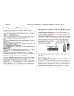
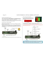
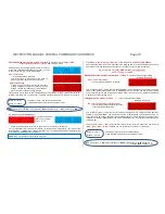
Master-Booster operation:
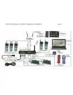
Up to 16 MX10 (or MX10EC) can work together as boosters with one MX10 (or MX10EC) as
digital command station.
Each MX10, both master (digital command station) and booster, has to be supplied by a po-
tential-
free power supply unit. We recommend ZIMO’s power supply units of 240 W or 600 W
(with real booster operation usually the more powerful one).
In the booster’s menu “MX10 CONFIG”, -> “SYS MODE”,
“B1”...”B16”
is configured. Each
booster device gets its own number. The system central command station keeps the configu-
ration “MASTER”.
The boosters are automatically synchronised with track output S1 of the central device; there-
by also BCS (broadcast stop) and OFF states are synchronised. As service mode program-
ming track, exclusively track output S2 of the central MX10 (master) can be used.


