background image

Inverter/Controller User Interface

Display

.................................................................................................

4 Line x 20 Character LCD, LED back lit

Keypad

............................................................................................................

5 Mechanical Switch keypad

Ethernet

...........................................................................................

10/100 Base T, SNMP and Internet capable

USB

..................................................................................................................

USB 2 for Flash Drives only

Relays

............................................................................

8 isolated Relays with NO and NC contacts, 2A @ 120 VAC

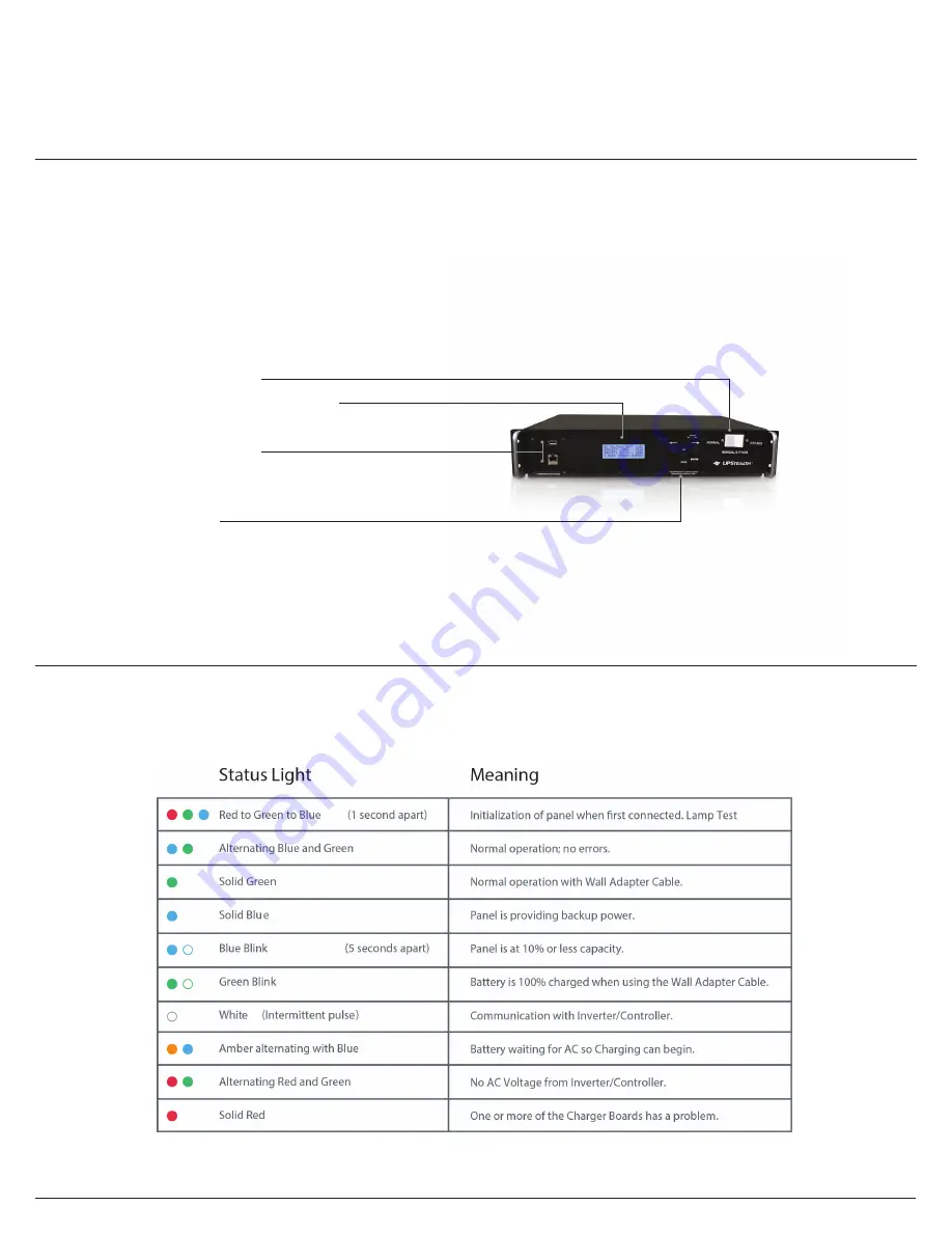
Battery Panel LED Information

Battery Panel Status:

The Battery Panels have a tri-color LED to indicate status information, as explained in the following table. 

Bypass Switch
Inverter/Controller Interface

USB Port
Ethernet Port

Keypad

UPStealth® 170 Inverter/Controller 

/

 UPSTEALTH® 

USER MANUAL


Summary of Contents for UpStealth

Page 1: ... 2017 ZincFive Inc support zincfive com Support 888 517 7776 User Manual ...

Page 2: ...UPStealth Support Call 888 517 7776 or email support zincfive com 0002 ...

Page 3: ...tus Screen Normal Status Display Power Failure Display Force On Display System Menu Overview Time and Date Menu Relay Selection Trigger View Menu System Description Relay Setup System Description Common Panel Save Panel On Off AC Trigger Menu Temperature Trigger Menu Flash Trigger Menu Time Trigger Menu Battery Capacity Menu Relay Status Menu Event Log Setting Power Failure Thresholds Sensitivity ...

Page 4: ...Battery Panel has built in intelligence which monitors battery performance charging maintenance and system status The Battery Panel consists of multiple strings of 48VDC NiZn batteries each string having its own intelligent charger monitor boards The failure of a single or multiple strings of battery cells within a panel will not disable the battery This redundancy greatly increases the UPStealth ...

Page 5: ...ntroller is available in two different physical configurations A NEMA version and a 170 version The NEMA Inverter Controller is made to sit on a shelf or be rack mounted All of the connectors keypad and LCD display are on the front of the unit The 170 Inverter Controller is 2U high and is rack mountable The connectors are on the back panel of the 170 unit and the LCD display keypad and Ethernet in...

Page 6: ...as an Ethernet interface for connection to a computer local area network or the Internet NTC IP is available for a SNMP network A USB port is also available so the software can be updated easily using a flash drive Each Battery Panel has a tri color LED to indicate battery status Battery Panels are charged through the Inverter Controller cable or independently through a cable that plugs into a sta...

Page 7: ...er UPStealth 170 Inverter Controller UPSTEALTH USER MANUAL 4 27 35 17 19 15 lbs 8 8 19 12 17 17 17 3 10 19 3 5 1 30 lbs 14 lbs 28 lbs 27 35 17 19 15 lbs 8 8 19 12 17 17 17 3 10 19 3 5 1 30 lbs 14 lbs 28 lbs Intelligent Two Stage System 6 milliseconds User can select up to 200 milliseconds 1000 Watts 1500 optional 3000 W for 30 cycles 120 VAC 60 Nominal 80 to 135 VAC 57 to 63 Hz 120 VAC 3 60 Hz 0 1...

Page 8: ... 2 for Flash Drives only Relays 8 isolated Relays with NO and NC contacts 2A 120 VAC Battery Panel LED Information Battery Panel Status The Battery Panels have a tri color LED to indicate status information as explained in the following table Bypass Switch Inverter Controller Interface USB Port Ethernet Port Keypad UPStealth 170 Inverter Controller 5 UPSTEALTH USER MANUAL ...

Page 9: ...o keep them separated you should not connect the AC neutral from the UPStealth to the AC Neutral of the utility power IMPORTANT If the UPStealth doesn t power up after the AC power is turned on check and make sure that the AC Power is connected correctly The unit will not power up if the AC power line is connected to its AC OUT terminals When a PIM is used in a system all connections are made to t...

Page 10: ......

Page 11: ......

Page 12: ...n on their outputs This happens within a few microseconds All of the battery string outputs are combined together to form one large battery A dead or partially discharged battery panel will not drag down the other panels Each battery string is current limited to prevent one battery string from supplying all of the power When the AC power is restored the UPStealth looks for good power stable wave f...

Page 13: ... Battery panels can be used in any orientation The Battery Panels can contain any number of battery strings but typically have four or six battery strings Each Battery Panel has an intelligent controller that gathers data from each battery string which is relayed back to the Inverter Controller Entering into power fail mode is independent of the panel controller so the battery strings can respond ...

Page 14: ...reduce the life of the panel Battery Panels can be added or removed at any time in a system Adding a discharged panel to a system will not hurt the system The UPStealth will adjust the capacity and run times when the UPStealth system detects the change in battery strings The Battery Panel rating 300 Watt and or 500 Watt is based on a discharge time of 2 hours A 500 Watt panel will supply a 250 Wat...

Page 15: ...ry ways to directly interact with an installed UPStealth while standing in front of the traffic cabinet the front panel LCD display and keypad on the front of the Inverter Controller or by connecting through the Ethernet port with a laptop with the installed RTi Connect desktop application Once connected through the Ethernet port the technician can see and manage the UPStealth parameters menu In a...

Page 16: ...sed on the cabinet load The percentage represents the overall charge state of the batteries Power Failure Display If a power failure occurs the following display is shown Force On Display If the UPStealth is started up with the Force On switch the display will first show The display will automatically switch to the Power Failure Display after the UPStealth has initialized itself Controls To get to...

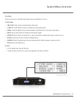
Page 17: ...figuration RELAYS Brings up the screen for viewing and setting relay triggers EVENT LOG Shows the past 74 system events such as power failure configuration change internal error etc MORE Provides access to the AC Switch and Ethernet Menus INVERTER Allows for configuring and viewing the brownout thresholds and power monitor sensitivity BACK Returns to the Main Screen Controls Use the direction keys...

Page 18: ... BACK Returns to the main system menu Controls To set the time Move the cursor over SET and press ENTER The cursor will now move into the time area of the screen Press UP DOWN to change a value If it reaches a maximum or minimum value the value will rollover e g if UP is pressed when the minutes is 59 it will go to 0 Press LEFT RIGHT to select a value such as hour min day etc When finished press E...

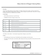
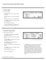
Page 19: ...ay RELAY Brings up the settings menu for that relay TRIGGER What the relay will trigger on Values can be In the below screenshot Relay1 is not configured to trigger Relay2 will trigger on a power failure Controls Use the direction keys to select a relay Press ENTER to go to the configuration screen for that relay The screen scrolls allowing access to all the relays BACK will always be at the very ...

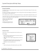
Page 20: ...ne There is a unique trigger panel for each trigger option Settings such as temperature bounds and times will be saved even when a trigger is turned off The following information is common to all applicable configuration screens Relay Setup and System Display UPStealth Interface Common Panel Except when saving this will be displayed on the left side of the screen On This Display RLY The relay that...

Page 21: ...o multiple triggers or scroll through the trigger panels looking at which box is checked at the bottom of the trigger pane Trigger is ON for that relay Trigger is OFF for that relay UPStealth Interface UPStealth Interface UPStealth Interface On This Display NO Changes will be discarded YES Changes will be saved and made active Controls Same as the Common Panel Notes The settings to be saved will b...

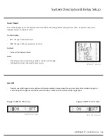
Page 22: ...Select SET The cursor will now be in the trigger pane Use the directional arrows to select ON or OFF Press ENTER The save menu will appear and the cursor will move to it Review changes and select YES The relay is now configured The Relay will stay enabled for the length of the Power Failure Temperature Trigger Menu To Setup a Temperature Trigger Select NEXT to get to the temperature trigger panel ...

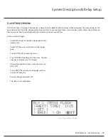
Page 23: ...re that has lasted a certain amount of time To Setup a Flash Trigger Select NEXT to get to the flash trigger panel if not already on it Select SET The cursor will now be in the trigger pane Press LEFT RIGHT to move the cursor Press UP DOWN to change the flash time The time changes in increments of 15 minutes After entering the flash time move the cursor to ON or OFF Press ENTER The save menu will ...

Page 24: ...ove the cursor to the value needing to be changed On this screen the cursor can move between the hours and minutes of the start and end times as well as the ON and OFF buttons Press UP DOWN to configure the times Note that the system uses military time After entering the start and end times move the cursor to ON or OFF Press ENTER The save menu will appear and the cursor will move to it Review cha...

Page 25: ...e cursor Press UP DOWN to change the capacity trigger point After entering the capacity point move the cursor to ON or OFF Press ENTER The save menu will appear and the cursor will move to it Review changes and select YES The relay is now configured Relay Status Menu Selecting STATUS from the Relay menu brings up the follows display The real time status of all 8 relays is shown on this display The...

Page 26: ...event In the pictured example a power failure it shows the duration of the event Controls Press LEFT or RIGHT to scroll through the event log To return to the main system menu press ENTER Notes The event log will show the newest event first The oldest event will be furthest to the right and the newest event will be furthest to the left The arrows on the top of the screen will reflect this If no ev...

Page 27: ...tive the power monitoring system is This can be one of five values as listed in the table below The sensitivity value will depend on the level of AC Line noise in the area and application SET Allows for configuring and viewing the brownout thresholds and sensitivity of the power monitor BACK Returns to the Main Screen Controls To set the thresholds and sensitivity Select SET and press ENTER The cu...

Page 28: ...t power failures you may not notice any reduction in battery life On This Display HIGH CAPACITY MODE The mark indicates if the mode is turned on or off SET Allows the mode to be turned on or off BACK Returns to the main system menu Controls To set high capacity mode Move the cursor over SET and press ENTER The cursor will now move into the on off area of the screen Press UP DOWN to change the valu...

Page 29: ...ted and initialized by the system An M in the box means a HUB with multiple panels is connected to the port Controls To enter panel detection mode Move the cursor over ADD PANEL and press ENTER The cursor will now move and the waiting menu will appear Connect panels and wait for the mark s to appear in the diagram Press ENTER when finished connecting Battery Panels It will not automatically exit d...

Page 30: ...itching times You might want some equipment to completely power down during a power failure The 00 ms time represents 6 msec The time can be set in 8 msec steps To set the delay time move the cursor to SET and Press ENTER Use the UP and Down keys to adjust the value and press ENTER Ethernet Communications The Ethernet Display shows the IP address and the MAC Address for the Ethernet Board There is...

Page 31: ...nth to maintain a good life expectancy A Battery Panel that has been connected to a cable but not charged for an extended period a week or so may not start on its own when connected to an AC source because its voltage has dropped too low A Panel in this condition will require a factory reset and should be returned to the factory for a recharge and retest IMPORTANT If the UPStealth doesn t power up...

Page 32: ...ide Varistor Transient Suppressor msec Milli seconds one thousandth of a second NC Normally Closed Contact circuit completed NEMA National Electrical Manufacturers Association Traffic Cabinet Nickel Zinc Rechargeable battery chemistry that uses Nickel and Zinc NiZn NO Normally Open Contact circuit not complete NTCIP National Transportation Communication for ITS Protocol PCB Printed Circuit Board P...

Page 33: ...UPStealth Support Call 888 517 7776 or email support zincfive com ...

Reviews: