14
Assembly
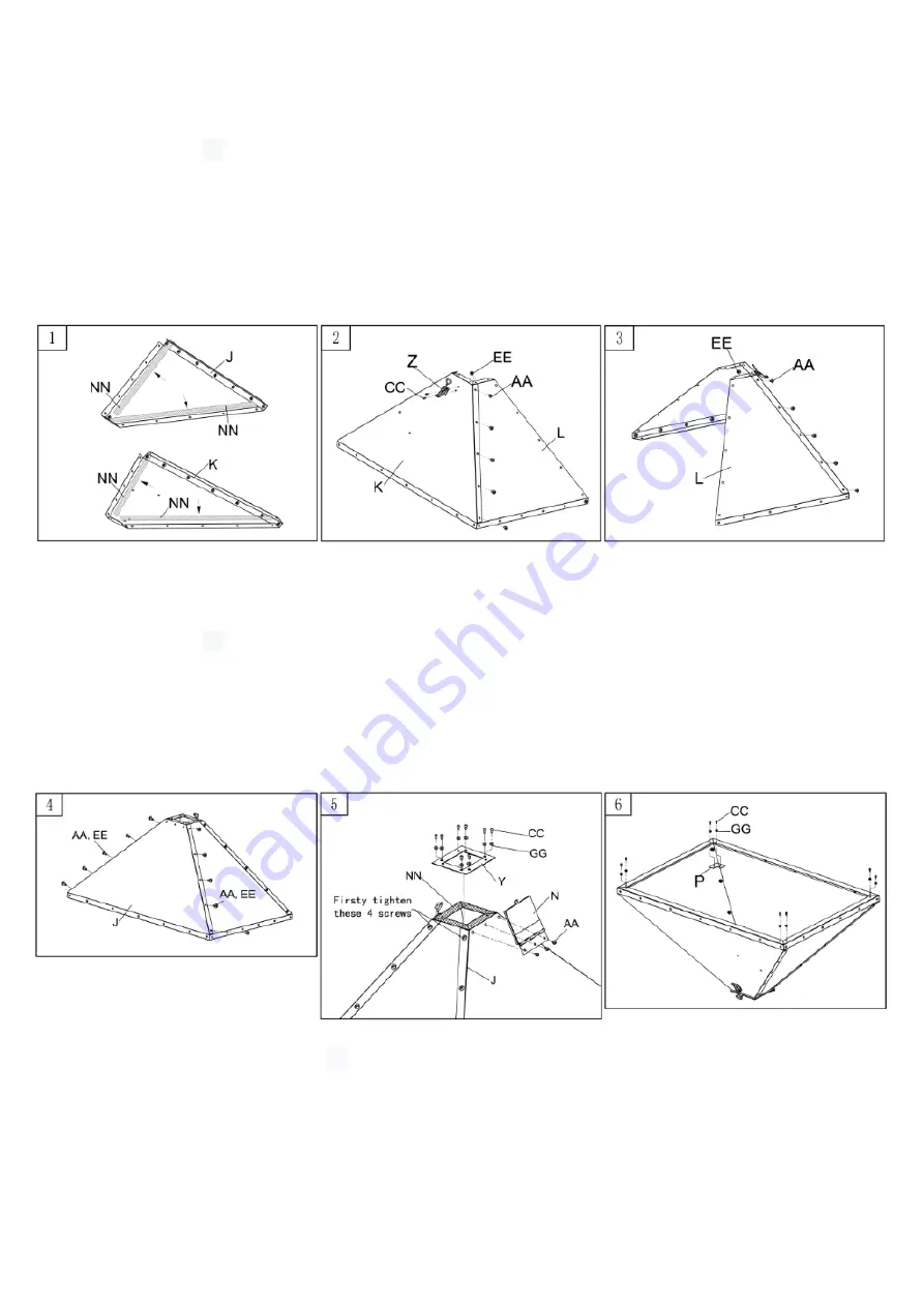
1.
Stick
δ3
sealing tape (NN, fig.1.1) onto the bended edge of the front plate (K, fig.1.1) and
back plate (J, fig.1.1) of the funnel as shown in fig 1.1.
2.
Use M4x10mm bolts (CC, fig.1.2) to mount the clamp (Z, fig.1.2) to the front funnel plate (K,
fig.1.2), firmly tighten. Mount the left funnel plate (L, fig.1.2) to the front funnel plate (K,
fig.1.2) with the M6x12mm bolts (AA, fig.1.2) and M6 nuts (EE, fig.1.2).
3.
Mount the right side plate (L, fig.1.3) to the front plate (K, fig.1.2) with the M6x12mm bolts
(AA, fig.1.2) and M6 nuts (EE, fig.1.2).
4.
Mount the rear plate (J, fig.2.4) to the side plates with the M6x12mm bolts (AA, fig.1.2) and
M6 nuts (EE, fig.1.2).
5.
Stick
δ3
sealing tape (NN, fig.2.5) on the bottom of the funnel and then mount the bottom
plate of the funnel (Y, fig.2.5) to the funnel with the 8 M4x10mm bolts (CC, fig.2.5) and Ø4
rings (GG, fig.2.5). Then mount the flip cover (N, fig.2.5) to the rear plate of the funnel with 3
M6x12mm bolts (AA, fig.2.5).
6.
Place a connector bracket (P, fig.2.6) in in all corners of the top of the funnel and mount with
8 M4x10mm bolts (fig.2.6) and Ø4 rings (GG, fig.2.6).
7.
As shown in fig.3.7 the
δ3
sealing tape (NN, fig.3.7) should be placed on both side plates (L,
fig.3.7) of the funnel, it should run through at least 30mm over the corners.
8.
Mount the left side panel (E, fig.3.8) against the funnel with 2 M6x12mm bolts (AA, fig.3.8),
do not fully tighten yet.
Fig.1
Fig.2


