15
9.
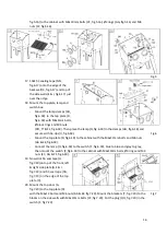
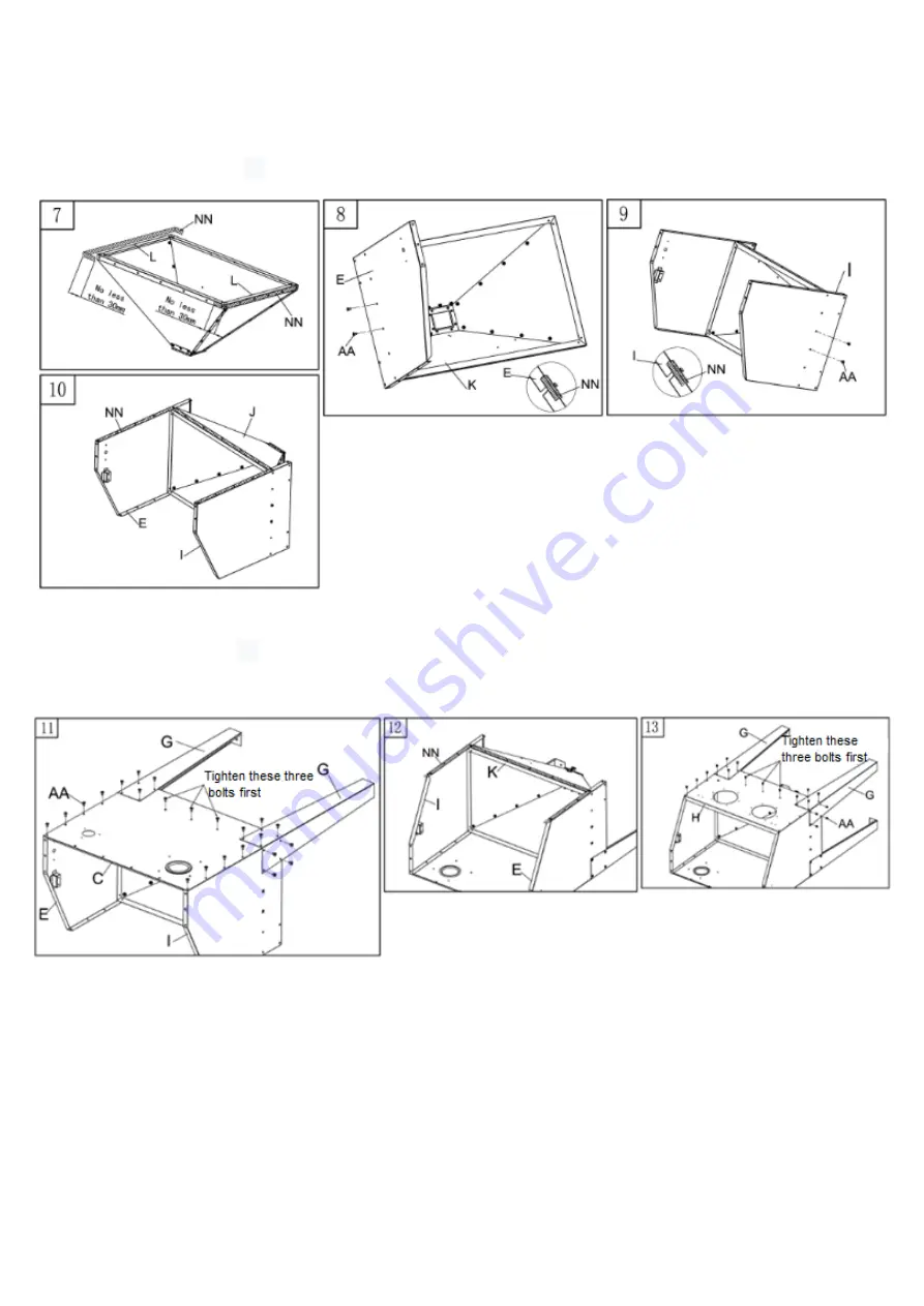
Mount the right side panel (I, fig.3.8) against the funnel with 2 M6x12mm bolts (AA, fig.3.8),
do not fully tighten yet.
10.
Now place
δ3
sealing tape (NN, fig.3.10) on the backside of the cabinet (E, I & J, fig.3.10).
11.
Mount the back (C, fig.4.11) and rear legs (G, fig.4.11) against the cabinet with M6x12mm
bolts (AA, fig.4.11), make sure the three bolts in the middle are tightened first.
12.
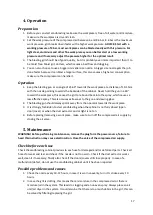
Now stick
δ3
sealing tape (NN, fig.3.12) against the front of the cabinet (E, I & K, fig.2.10).
13.
Mount the front panel (H, fig.4.11) and front legs (G, fig.4.11) to the cabinet with M6x12mm
bolts (AA, fig.4.11), make sure the three bolts in the middle are tightened first.
14.
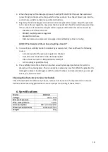
Now put the cabinet on its legs, now mount the grid, pickup tube and sandblasting gun.
-
Connect the sand hose (place through grid) to the pickup tube (O, fig.5.14) and mount
the pickup tube to the front plate of the funnel (K, fig.5.14) with 2 M6x12mm bolts (AA,
fig.5.14) and M6 nuts (EE, fig.5.14).
-
Connect the air hose nipple with the nut, use teflon tape to make the connection airtight.
15.
Mount the gloves (R, fig.5.15), first mount the glove seats (V & U, fig.5.15). tehn attach the
gloves (R, fig.5.15) to the glove seats (V, fig.5.15) with the clamps (S, fig.5.15).
16.
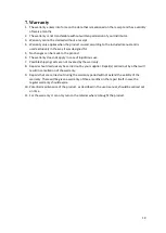
Mount the flange (KK, fig.5.16) with the M4x16mm bolts (BB, fig.5.16), Ø4 rings (GG, fig.5.16)
and M4 nuts (FF, fig.5.16). Mount the inlet box (X, fig.5.16)to the rear wall of the cabinet with
4 M6x12mm bolts (AA, fig.5.16) and M6 nuts (EE, fig.5.16). Then mount the clamps (M,
Fig.3
Fig.4


