16
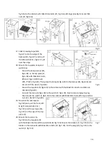
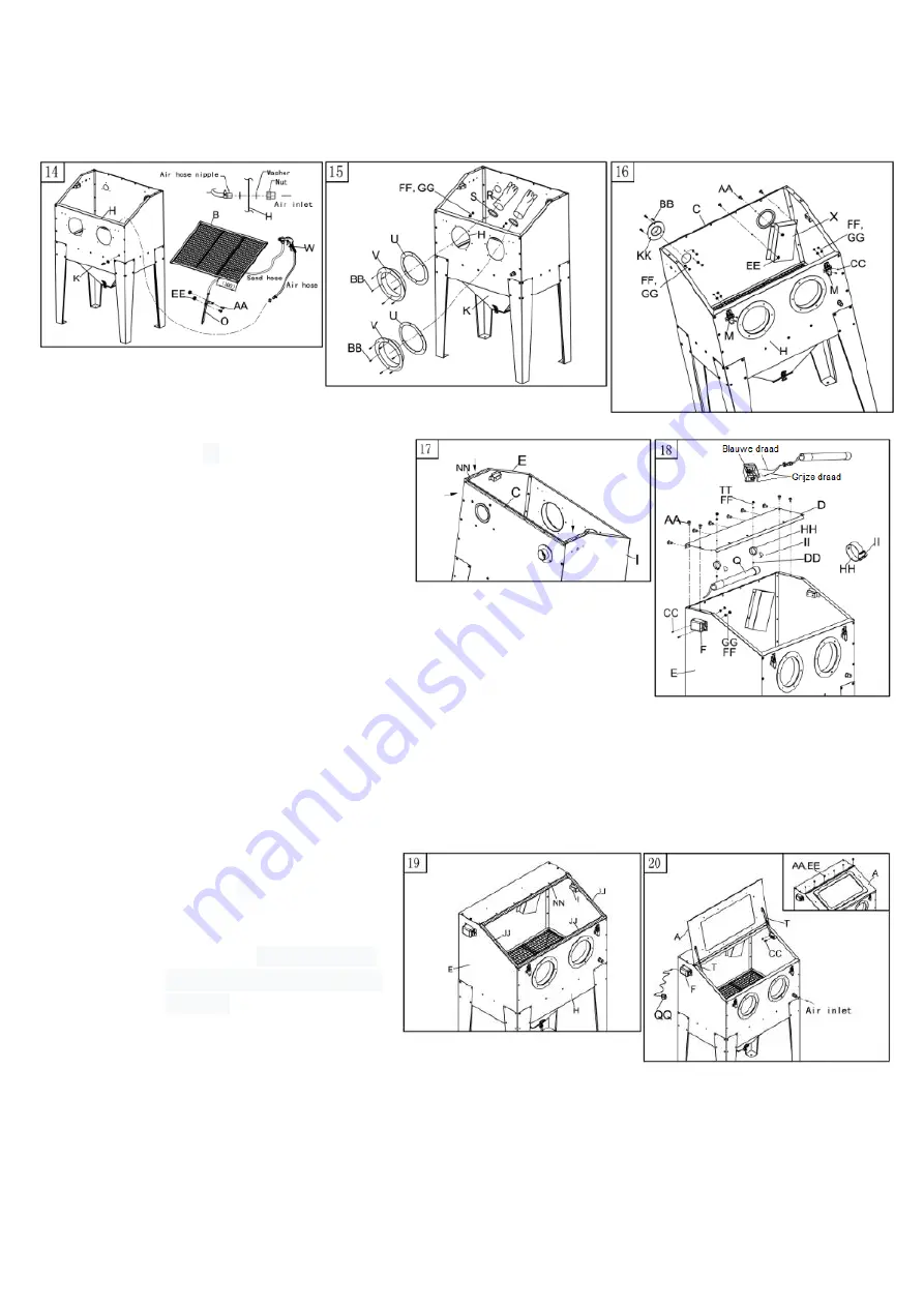
fig.5.16) to the cabinet with M4x10mm bolts (CC, fig.5.16), Ø4 rings (GG, fig.5.16) and M4
nuts (FF, fig.5.16).
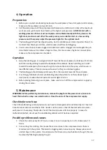
17.
Stick
δ3
sealing tape (NN,
fig.6.17) onto the edge of the
back wall (C, fig.6.17) and top of
the side walls (E & I, fig.6.17) just
over the ridge.
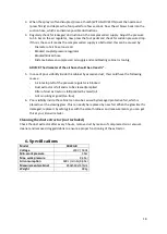
18.
Mount the top plate, lamp and
switch box:
-
Mount the lamp clamps (HH,
fig.6.18) to the top plate (D,
fig.6.18) with M4x6mm bolts,
Ø4 lock rings and M4 nuts
(DD, TT & FF, fig.6.18). Then place the lamp (Q, fig.6.18) in the clamps (HH, fig.6.18) and
secure with tie-rips (II, fig.6.18).
-
Mount the top plate (D, fig.6.18) to the cabinet with the M6x12mm bolts and M6 nuts
(AA & EE, fig.6.18).
-
Connect the lamp (Q, fig.6.18) to the switch (F, fig.6.18), blue to blue and grey to grey,
then mount the switch (F, fig.6.18) to the cabinet with M4x10mm bolts, Ø4 rings and M4
nuts (CC, GG & FF, fig.6.18).
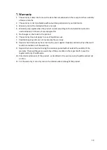
19.
Now stick
δ6
seal tape (JJ,
fig.7.19)on top of the front, left
& right side plate (H, E & I,
fig.7.19) and
δ3 seal tape (NN,
fig.7.19) on the edge of the top
plate (D).
20.
Mount the top door (A,
fig.7.20) to the top plate (D)
with the M6x12 bolts and M6 nuts (AA & EE, fig.7.20). Mount the brackets (T, fig.7.20) to the
blocks on the side walls with M4x10mm bolts (CC, fig.7.20). Put the plug (QQ, fig.7.20) in the
switch (F, fig.7.20).
Fig.5
Fig.6
Fig.7


