12
807066 v1.01 08.21 HBP AB 21 Install Instructions
40L models
Heating
Element
Key
/x = x number of wires
Red = Red wire
Blu = Blue wire
Blk = Black wire
Grn = Green wire
Yel = Yellow wire
Brn = Brown wire
M
ai
ns
i
nput
806010 v3
Electrical Wiring Diagram
HydroBoil UK/DE/CN/Export –
40L
1(Red)
2(Blu)
2(Blu)
1(Red)
Overload
Chassis
Earth Tab
N
E
L2
L1 L2 L3 L4
T1 T2 T3 T4
Contactor
A1
A2
2
Heating
Element
Red/Blk
L1
Brn
Brn
1
1
Bl
k
Bl
k
Bl
k
Grn/Yel
Brn
Brn
Bl
k
Blu
Thermostat
Bl
k
Re
d
Re
d
Bl
k
2
Brn
80481
5
Heating
Indicator
S
ingl
e
P
has
e
C
o
nnec
ti
on
380-415V AC, 3-phase
4.4
Heating
Element
Key
/x = x number of wires
Red = Red wire
Blu = Blue wire
Blk = Black wire
Grn = Green wire
Yel = Yellow wire
Brn = Brown wire
M
ai
ns
i
nput
806010 v3
Electrical Wiring Diagram
HydroBoil UK/DE/CN/Export –
40L
1(Red)
2(Blu)
2(Blu)
1(Red)
Overload
Chassis
Earth Tab
N
E
L2
L1 L2 L3 L4
T1 T2 T3 T4
Contactor
A1
A2
2
Heating
Element
Red/Blk
L1
Brn
Brn
1
1
Bl
k
Bl
k
Bl
k
Grn/Yel
Brn
Brn
Bl
k
Blu
Thermostat
Bl
k
Re
d
Re
d
Bl
k
2
Brn
80481
5
Heating
Indicator
S
ingl
e
P
has
e
C
o
nnec
ti
on
220-240V AC, 1-phase
4.3
Step 4 – Electrical connection
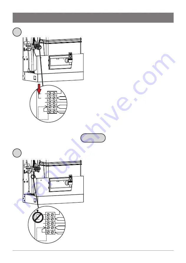
Single-phase power supply
15-25L models:
These models have single-
phase connection. No bridging is required.
40L models:
There are two connection
options:
• Single phase 220-240V. L1 and L2 need
to be bridged on installation. The single
phase supply must be sufficient to handle
the power of the unit (i.e. 25A or above)
• 3 phase connection (see below)
3-phase power supply
40L models:
There are two connection
options:
• Single phase 220-240V (see above)
• 3 phase connection 380-415V. 2 out of 3
phases are connected to L1 and L2. No
bridging between L1 and L2 is required
OR


